Installing an at-lx3811/x line card, Figure 22. removing the dust covers – Allied Telesis AT-LX3800U User Manual
Page 50
Chapter 2: Installation
50
Installing an AT-LX3811/x Line Card
To install an AT-LX3811/x line card, perform the following procedure:
Note
The AT-LX3811 line cards are numbered and color-coded for
insertion in the corresponding numbered and color-coded slot in the
chassis. The RDY LED on the line card flashes green and the
AT-S65 management software displays an error if a line card is
inserted in the wrong slot.
1. Remove the AT-LX3811/x line card from its shipping package and
store the package in a safe place.
You must use the original package if you need to return the unit to
Allied Telesyn.
2. Select the slot in the AT-LX3800U chassis that corresponds to the
number of the line card you want to install.
3. Remove any AT-LX3801 Blank Slot Cover from the slot.
Keep the blank slot cover in a safe area in case you remove the line
card. The blank slot cover protects the fiber optic connectors on the
backplane from becoming dirty, and helps maintain proper air flow
through the chassis.
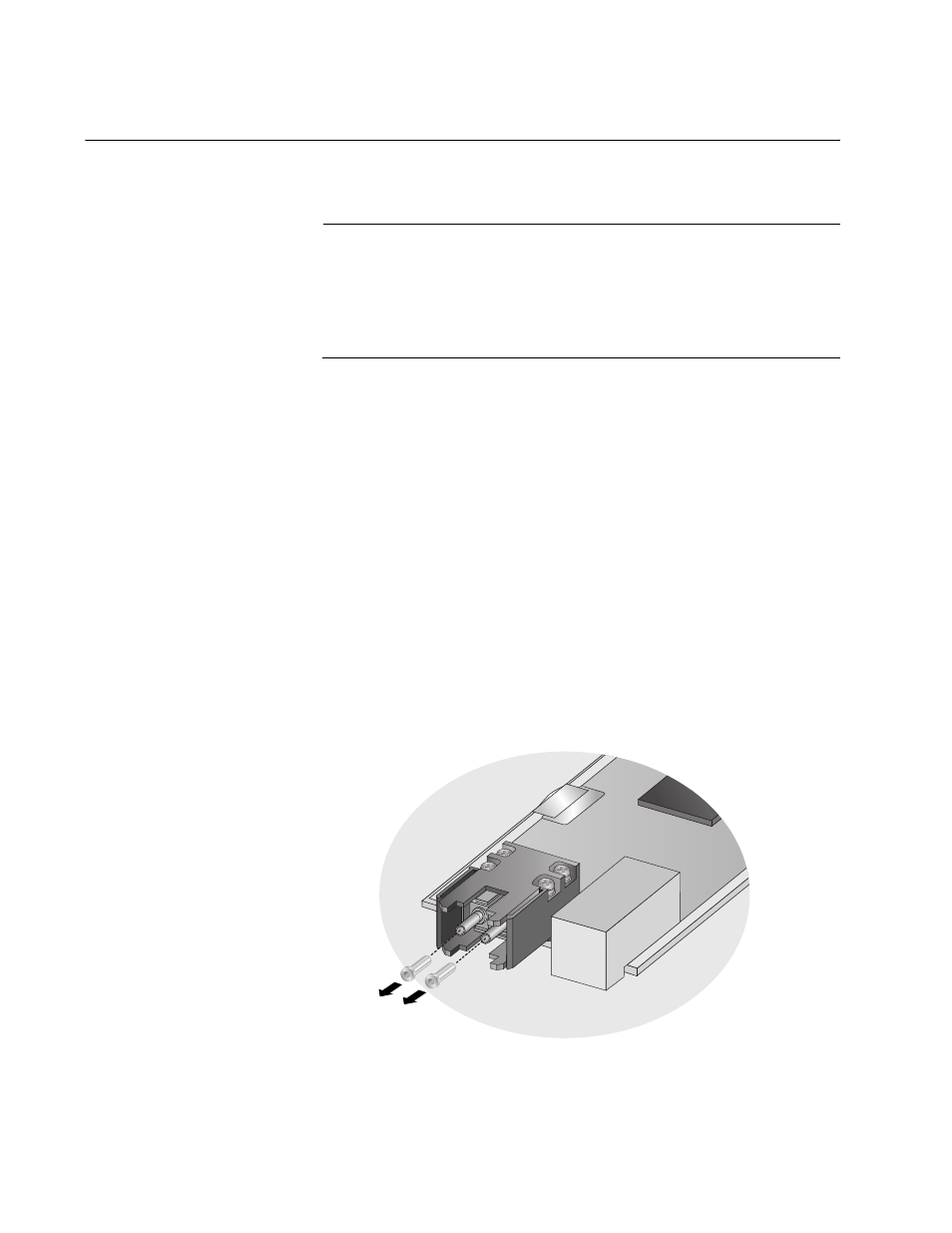
4. Remove the dust caps from the fiber optic connectors at the back of
the line card, as shown in Figure 22.
Figure 22. Removing the Dust Covers
173