Allied Telesis 9400 iMAP User Manual
Page 6
Overview
ATI 9400 Configuration
Telesyn x400 - Installation Guide (Installation of ATI 9400)
1-2
.
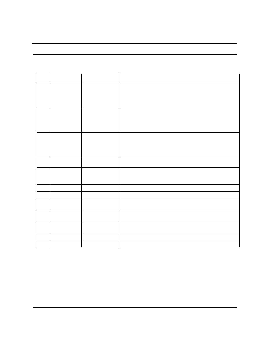
TABLE 1-1
Listing of components with slot/position and configuration notes
No.
Module
Slot/Position
Configuration Notes
A
Service Module
(SM)
6, 8, 10 (left)
5, 7, 9,11 (right)
At least one is always configured. Unused slots must be configured
with FPFs.
Note: For information on SMs supported on the 9400 refer to the ATI
Component Reference.
B
Control Module
(CM)
2, 4 (double)
One card per shelf (occupies two slots).
Includes RS232 and OAM port. ETH0 and ETH1 are not used.
Note: For information on CMs supported on the 9400 refer to the ATI
Component Reference.
C
Network Mod-
ule (NM)
Slot 0 and Slot 1
At least one is always configured. A Small Form Factor Pluggable
(SFP) module is required. An unused half-slot requires an FPH.
Note: For information on NMs supported on the 9400 refer to the ATI
Component Reference.
D
Fan Controller
3 (half-slot)
Fan Controller. Includes ALM IN port and ALM OUT port. COMM
port is currently not used.
E
Power Entry
Module
Lower right of
chassis
Power Entry Module. Includes power feeds (H), signal ground, returns
(I), and A/B circuit breakers. (Signal ground is only used in an Isolated
Bonding Network.)
F
Fan Module
Center of chassis
Fan Module.
G
ESD
ESD wrist strap connection point.
NA
MAC
Inside Chassis
Included with chassis. Located on the front of backplane behind slots 8
and 10.
NA
FPF
Panels for Service
Module
Required when a Service Module slot is not used. Ensures proper air-
flow and EMI compliance.
NA
FPH
Panel for Network
Module
Required when half-slot for Network Module is not used. Ensures
proper airflow and EMI compliance.
H
-
-
Mounting hole group.
I
Ground
Right side
Primary ground connection