13 install the service module, 14 install the network module, 13 install the service module -20 – Allied Telesis 9400 iMAP User Manual
Page 24: 14 install the network module -20
Install the Service Module
Install the Chassis
Telesyn x400 - Installation Guide (Installation of ATI 9400)
1-20
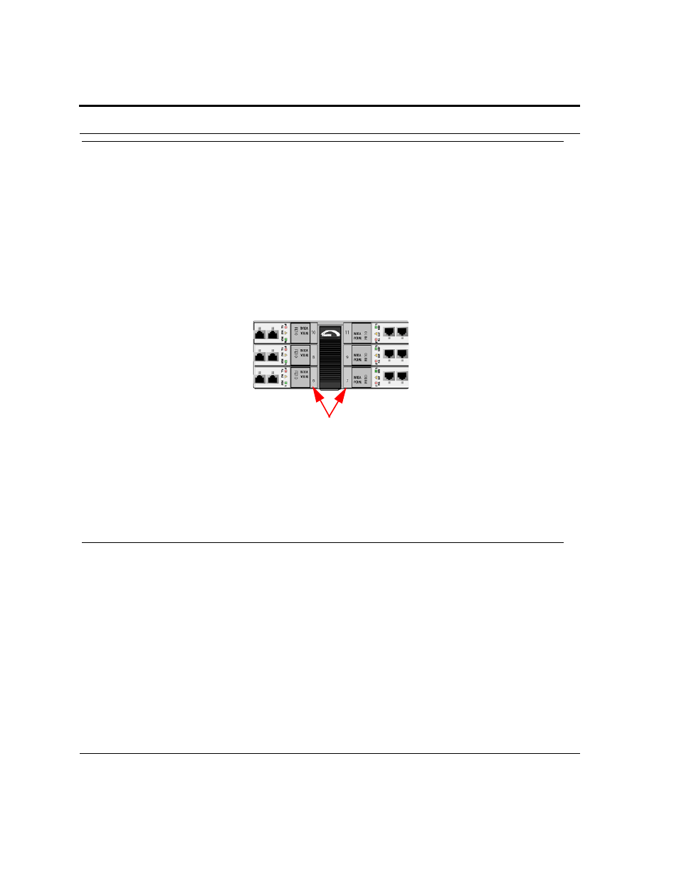
1.13 Install the Service Module
Note:
This example is for the FE10, but it can be applied to any SM supported by the 9400 system.
The Service Modules can be placed in any of the following slots: 6, 8, 10 (left), and 5, 7, 9, 11 (right). It is rec-
ommended that the slots be filled in numerical order slot 5-11.
1.
Take the card from its antistatic container.
2.
For insertion into slots 6, 8, or 10, hold the card securely with component side down. For insertion into slots
5, 7, 9, or 11, hold the card by its latches with component side up. (For any slot, the latch/label will go on the
inside of the chassis). Refer to Figure 1-16.
FIGURE 1-16
For 9400 SM Cards, Latch Label on Inside of Chassis
3.
Press the release buttons on the inside of the latches and push the latches out. (Refer to Figure 1-14.)
4.
While holding the card, slowly but firmly push the card into the slot until the latches begin to engage the
locking rail.
5.
Close the latches until the card locks into place.
1.14 Install the Network Module
Note:
This procedure can be applied to any NM supported on the 9400.
The Network Module(s) go into Slots 0 and 1. It is recommended that Slot 0 be filled first.
1.
Take the card from its antistatic container.
2.
Hold the card securely with component side down (lock-latch and label on the inside of the chassis)
3.
Locate the half-slot where the card is to be inserted.
4.
Press the release button on the inside of the latch and push the latch out. (Refer to Figure 1-14.)
5.
While holding the card, slowly but firmly push the card into the slot until the latch begins to engage the lock-
ing rail.
PULL
FAUL
T
INSERV
FE10
TN-100-ATN-100-A
Slot Numbers