8 connect grounding, 8 connect grounding -14 – Allied Telesis 9400 iMAP User Manual
Page 18
Connect Grounding
Install the Chassis
Telesyn x400 - Installation Guide (Installation of ATI 9400)
1-14
1.8 Connect Grounding
The primary ground for the ATI 9400 shelf is a grounding stud located on the right side of the chassis mounting
block (it will have the grounding symbol
).
Note:
There is only one grounding procedure, since the Logic Ground is done using the supplied
bonding strap.
1.
Using a 12 awg grounding cable (green with yellow stripe), connect the chassis grounding stud to office pri-
mary ground using two nuts or a lock washer and a nut (for two secured points). Connect the wire to the
grounding stud using a double crimp terminal (PANDUIT PMNF6-4R or equivalent). Refer to Figure 1-11
Note:
Torque setting for the grounding stud nut is 22.0 in. lb. (2.5 N*m) MAX. When tightening the
outer nut, ensure that the inner nut is held securely.
2.
Since the signal and primary office grounds are to be combined, installation is complete, which means:
1.
Leave the bonding strap connected to the center terminal of the terminal block in place.
2.
Do not connect anything else to the center terminal of the terminal block. Refer to Figure 1-10.
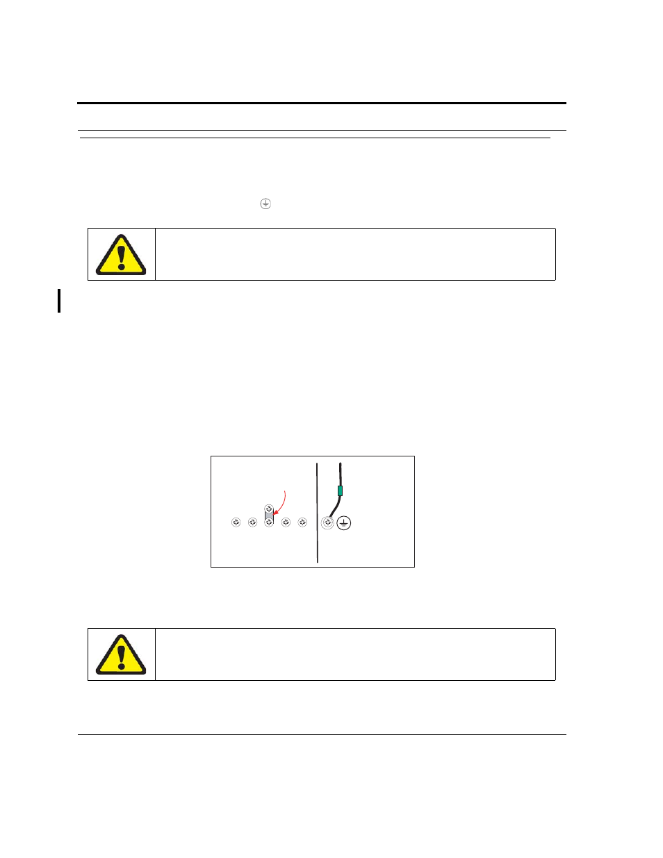
FIGURE 1-10
Single Grounding Configuration
The separate protective earthing terminal provided on this product
shall be permanently connected to earth.
The metal strap must be securely tightened using the two supplied
screws for the unit to function properly.
-48A
-48B LGND
RETB
RETA
Metal strap
Connection to primary
grounding post
PEM7
Primary grounding post
on chassis