Figure 25: attaching the equipment rack brackets – Allied Telesis AT-IX5-28GPX User Manual
Page 68
Chapter 4: Installing the Switch and its Power Supplies
68
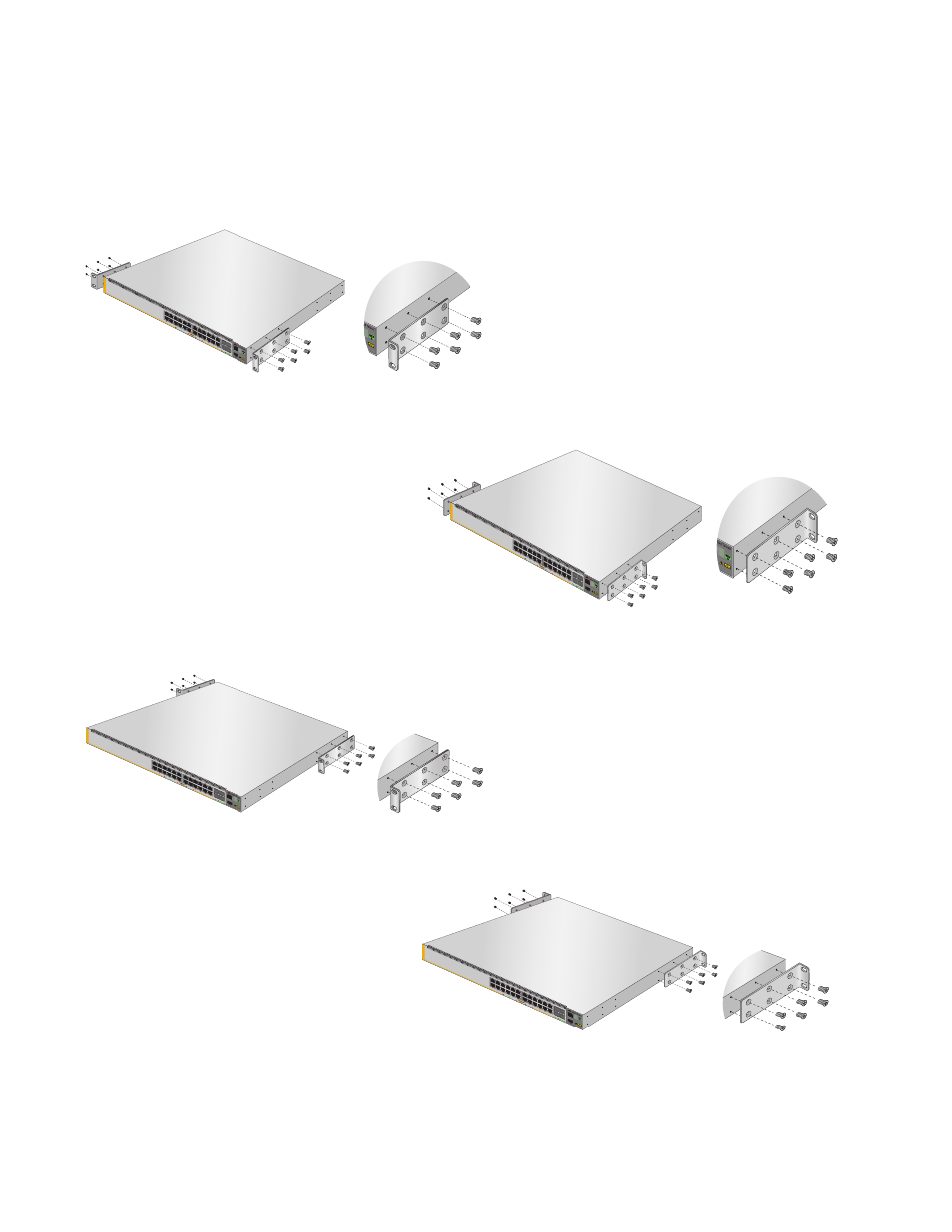
3. Turn the switch over.
4. Attach the two rack mount brackets to the sides of the switch using the
bracket screws included with the unit. Figure 25 on page 68 illustrates
the four possible bracket positions.
Figure 25. Attaching the Equipment Rack Brackets
2672
S2/
28
S1/
27
26
25
CO
NS
OL
E
IX5-28GPX
FDX
HDX
COL
1000
LIN
K
ACT
10/1
00 L
INK
ACT
SF
P+
S2/2
8
S1/
27
26
25
CO
NS
OL
E
IX5-28GPX
FDX
HDX
CO
L
1000
LIN
K
ACT
10/1
00 L
INK
ACT
SFP
+
2672
S2/
28
S1/
27
26
25
CO
NS
OLE
IX5-28GPX
FDX
HDX
C
OL
1000
LIN
K
ACT
10/1
00 L
INK
ACT
SFP
+
S2/
28
S1/
27
26
25
CO
NS
OL
E
IX5-28GPX
FDX
HDX
CO
L
1000
LIN
K
ACT
10/1
00 L
INK
ACT
SF
P+
See also other documents in the category Allied Telesis Computer hardware:
- AT-GS908M (54 pages)
- AT-x230-10GP (80 pages)
- AT-GS950/48PS (64 pages)
- AT-GS950/10PS (386 pages)
- AT-GS950/16PS (386 pages)
- AT-GS950/48PS (386 pages)
- AT-9000 Series (258 pages)
- AT-9000 Series (1480 pages)
- IE200 Series (70 pages)
- AT-GS950/48 (410 pages)
- AT-GS950/8 (52 pages)
- AT-GS950/48 (378 pages)
- AT-GS950/48 (60 pages)
- SwitchBlade x8106 (322 pages)
- SwitchBlade x8112 (322 pages)
- SwitchBlade x8106 (240 pages)
- SwitchBlade x8112 (240 pages)
- AT-TQ Series (172 pages)
- AlliedWare Plus Operating System Version 5.4.4C (x310-26FT,x310-26FP,x310-50FT,x310-50FP) (2220 pages)
- FS970M Series (106 pages)
- 8100L Series (116 pages)
- 8100S Series (140 pages)
- x310 Series (116 pages)
- x310 Series (120 pages)
- AT-GS950/24 (366 pages)
- AT-GS950/16 (44 pages)
- AT-GS950/24 (404 pages)
- AT-GS950/16 (404 pages)
- AT-GS950/16 (364 pages)
- AT-GS950/8 (404 pages)
- AT-GS950/8 (364 pages)
- AT-GS950/8 (52 pages)
- AT-8100 Series (330 pages)
- AT-8100 Series (1962 pages)
- AT-FS970M Series (330 pages)
- AT-FS970M Series (1938 pages)
- SwitchBlade x3106 (288 pages)
- SwitchBlade x3112 (294 pages)
- SwitchBlade x3106 (260 pages)
- SwitchBlade x3112 (222 pages)
- AT-S95 CLI (AT-8000GS Series) (397 pages)
- AT-S94 CLI (AT-8000S Series) (402 pages)
- AT-IMC1000T/SFP (23 pages)
- AT-IMC1000TP/SFP (24 pages)
- AT-SBx3106WMB (44 pages)