Front and rear panels, Power supply module bay 1, Power supply module bay 2 – Allied Telesis AT-IX5-28GPX User Manual
Page 19
IX5-28GPX Installation Guide
19
Front and Rear Panels
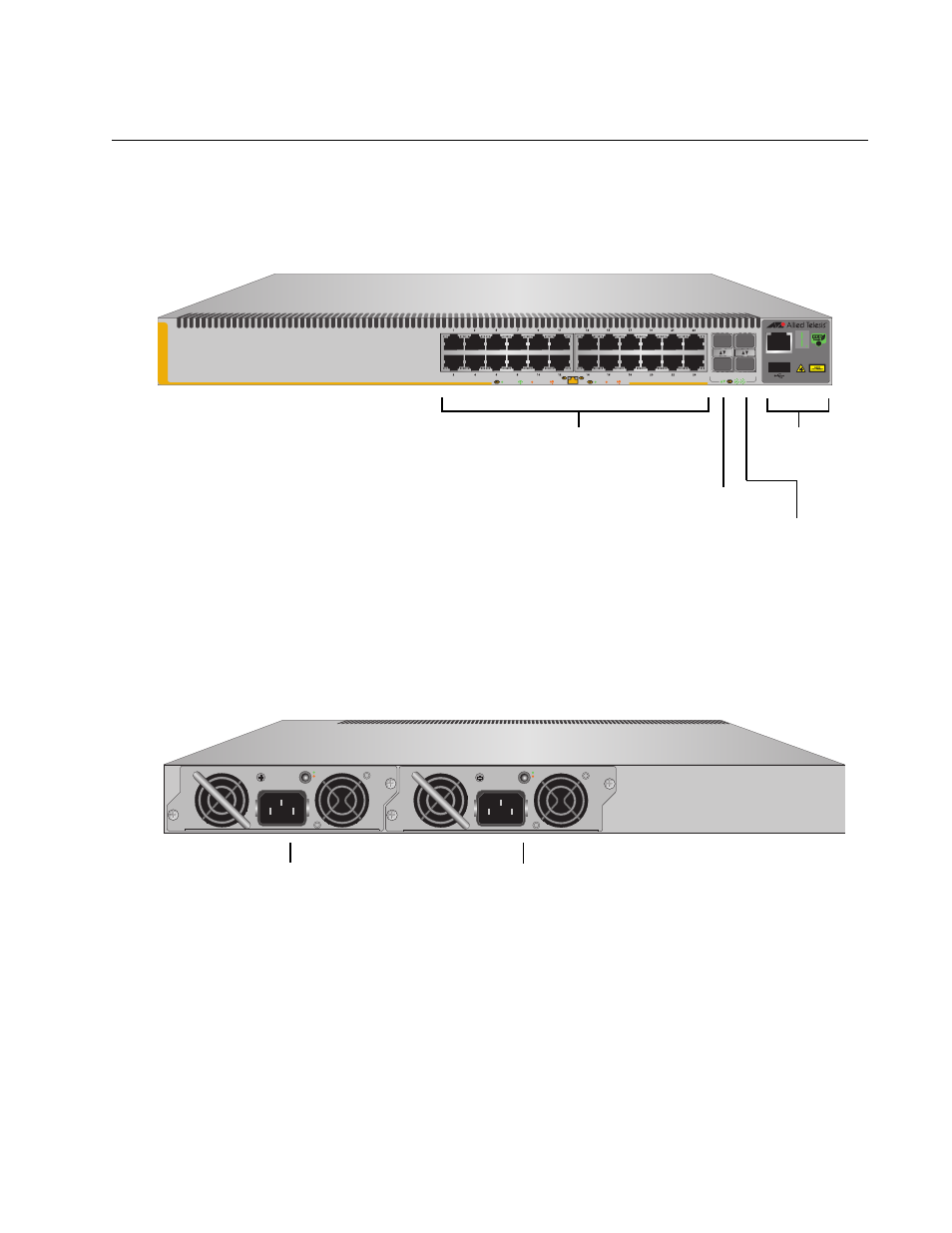
The front panel of the AT-IX5-28GPX switch is shown in Figure 1.
Figure 1. Front Panel of the AT-IX5-28GPX Switch
Figure 2 on page 19 shows the back panel.
Figure 2. Back Panel of the Switch
10/100/1000Base-T Ports
SFP+ Slots
Management
Panel
SFP+ or
Stacking Slots
S2/28
S1/27
26
25
CONSOLE
2661
IX5-28GPX
FDX
HDX COL
1000 LINK
ACT
10/100 LINK
ACT
SFP+
Power Supply Module
Bay 1
2001
100-240VAC~ 5A MAX
DC PWR
FAULT
A
T
-PWR800
100-240VAC~ 5A MAX
DC PWR
FAULT
A
T
-PWR800
Power Supply Module
Bay 2
See also other documents in the category Allied Telesis Computer hardware:
- AT-GS908M (54 pages)
- AT-x230-10GP (80 pages)
- AT-GS950/48PS (64 pages)
- AT-GS950/10PS (386 pages)
- AT-GS950/16PS (386 pages)
- AT-GS950/48PS (386 pages)
- AT-9000 Series (258 pages)
- AT-9000 Series (1480 pages)
- IE200 Series (70 pages)
- AT-GS950/48 (410 pages)
- AT-GS950/8 (52 pages)
- AT-GS950/48 (378 pages)
- AT-GS950/48 (60 pages)
- SwitchBlade x8106 (322 pages)
- SwitchBlade x8112 (322 pages)
- SwitchBlade x8106 (240 pages)
- SwitchBlade x8112 (240 pages)
- AT-TQ Series (172 pages)
- AlliedWare Plus Operating System Version 5.4.4C (x310-26FT,x310-26FP,x310-50FT,x310-50FP) (2220 pages)
- FS970M Series (106 pages)
- 8100L Series (116 pages)
- 8100S Series (140 pages)
- x310 Series (116 pages)
- x310 Series (120 pages)
- AT-GS950/24 (404 pages)
- AT-GS950/24 (366 pages)
- AT-GS950/16 (44 pages)
- AT-GS950/16 (404 pages)
- AT-GS950/16 (364 pages)
- AT-GS950/8 (404 pages)
- AT-GS950/8 (364 pages)
- AT-GS950/8 (52 pages)
- AT-8100 Series (1962 pages)
- AT-8100 Series (330 pages)
- AT-FS970M Series (330 pages)
- AT-FS970M Series (1938 pages)
- SwitchBlade x3106 (288 pages)
- SwitchBlade x3112 (294 pages)
- SwitchBlade x3106 (260 pages)
- SwitchBlade x3112 (222 pages)
- AT-S95 CLI (AT-8000GS Series) (397 pages)
- AT-S94 CLI (AT-8000S Series) (402 pages)
- AT-IMC1000T/SFP (23 pages)
- AT-IMC1000TP/SFP (24 pages)
- AT-SBx3106WMB (44 pages)