24'-28' wings – Summers Disk-Chisel User Manual
Page 26
WING
7/13/2012
9CC2412H.iam/
8CC5049
8T3600
8X0234
7/16" LNUT
8C6015
8X0044
7/16" X 3-1/2"
8K5515
3/4 X 4 X 6"
8X0306
3/4" LW
8X0260
3/4" N
8K1683
8T4224
8X0285
1 1/2" N
12
6
1/2"
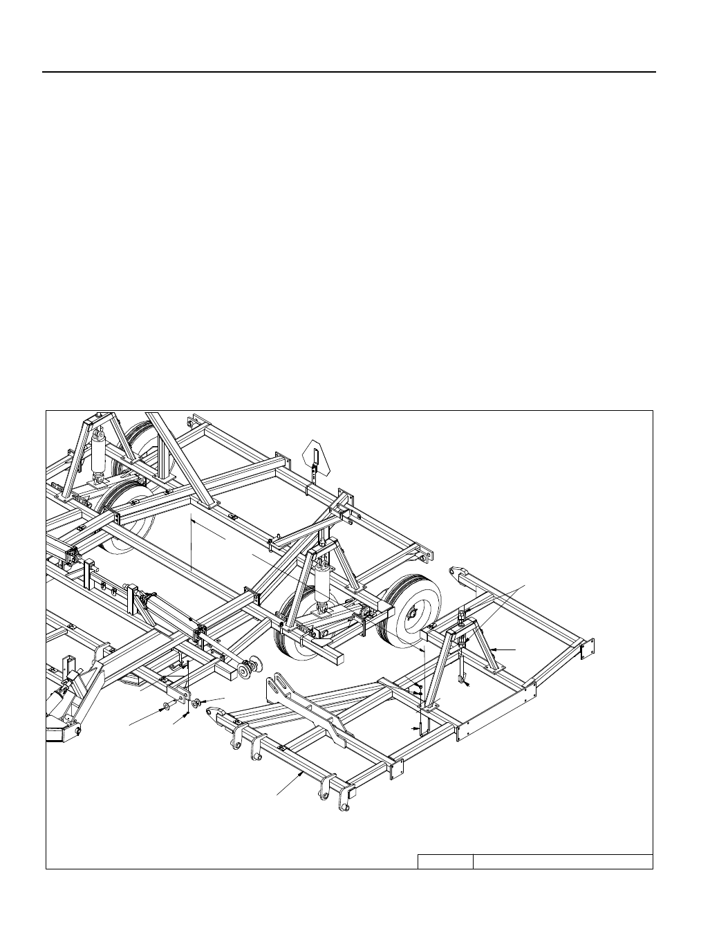
SECTION 2 – SET-UP OF 24’-28’ DISK-CHISEL & COULTER-CHISEL WINGS
2-14
NOTE: It is recommended to set up both sides of machine at the same time. The left hand side is
shown.
1. Attach wing to center section with pins, washers, bolts and locknuts.
– Washers are used to center wing in hinges and prevent shift.
2. Fasten cylinder attach brackets with 3/4” u-bolts, located 126-1/2” from machine center.
3. Insert eyebolts (8K1683) into cylinder attach bracket.
– Tighten 1-1/2” nuts so the same amount of threads are above top nut on all eyebolts. Insure
that cylinder attach holes are aligned when eyebolts are tightened.
4. Center liftarm under cylinder attach brackets.
– Use 3/4” u-bolts for 4x4 to attach liftarm pivots (8T4100) to frame.
– The inside pivot will be attached with 3/4 x 6” bolts and a trip assembly.
– Slide pivot pin (8T3640) through liftarm and liftarm pivots.