General specifications – Red Lion PXU User Manual
Page 3
33
GENERAL SPECIFICATIONS
1. DISPLAY: LCD negative image transmissive with backlighting. Top
(process) display with orange backlighting, bottom (parameter) display with
green backlighting.
Line 1 and 2: 4 digits each line
Status Annunciators:
OUT1 - Control output 1 is active.
OUT2 - Control output 2 is active.
ALM1 - Alarm 1 output is active.
ALM2 - Alarm 2 output is active.
ALM3 - Alarm 3 output is active.
°F, °C - Temperature units.
MAN - Controller is in Manual Mode.
AT - Auto-Tune active.
1/4 DIN Model Digit Size: Line 1 - 0.87" (22 mm); Line 2 - 0.55" (14 mm)
1/8 DIN Model Digit Size: Line 1 - 0.47" (12 mm); Line 2 - 0.47" (12 mm)
1/16 DIN Model Digit Size: Line 1 - 0.43" (11 mm); Line 2 - 0.27" (7.0 mm)
2. POWER:
Line Voltage Models:
100 to 240 VAC -20/+8 %, 50/60 Hz, 5 VA
Low Voltage Models:
DC Power: 24 VDC, ±10%, 5 W
3. KEYPAD: Mylar overlay with 4 program/selection keys and 2 user
programmable function keys. 6 keys total.
4. Display Messages:
- Measurement exceeds + sensor range
- Measurement exceeds - sensor range
- Open sensor is detected (TC or RTD)
- Shorted sensor is detected (RTD only)
. . .
- Display value exceeds + display range
. .. .
- Display value exceeds - display range
5. SENSOR INPUT:
Sample Period: 100 msec (10 Hz rate)
A/D Converter: 16 bit resolution
Span Drift (maximum): 130 PPM/°C
Input Fail Response:
Main Control Output(s): Programmable preset output
Display:
OPEN
,
sHrt
Alarms: programmable for On or Off
Normal Mode Rejection: >35 dB @ 50/60 Hz
Common Mode Rejection: >120 dB, DC to 60 Hz
6. INPUT CAPABILITIES:
Temperature/RTD Indication Accuracy:
± (0.3% of span, +1°C) at 25°C ambient after 20 minute warm up. Includes
NIST conformity, cold junction effect, A/D conversion errors and
linearization conformity.
THERMOCOUPLE INPUTS:
Types: T, E, J, K, R, S, B, N, L, U, and TXK
Input Impedance: Approximately 4.7 MΩ
Lead Resistance Effect: -0.3 µV/Ω
Cold Junction Compensation: Less than ±1.5°C typical (2.5°C max)
error over 0 to 50°C temperature range.
Resolution: 1° for types R, S, B and 1° or 0.1° for all other types
TYPE
DISPLAY RANGE
WIRE COLOR
STANDARD
ANSI
BS 1843
T
-200 to +400°C
-328 to +752°F
(+) Blue
(-) Red
(+) White
(-) Blue
ITS-90
E
0 to 600°C
+32 to +1112°F
(+) Violet
(-) Red
(+) Brown
(-) Blue
ITS-90
J
-100 to +1200°C
-148 to +2192°F
(+) White
(-) Red
(+) Yellow
(-) Blue
ITS-90
K
-200 to +1300°C
-328 to +2372°F
(+) Yellow
(-) Red
(+) Brown
(-) Blue
ITS-90
R
0 to +1700°C
+32 to +3092°F
No
standard
(+) White
(-) Blue
ITS-90
S
0 to +1700°C
+32 to +3092°F
No
standard
(+) White
(-) Blue
ITS-90
B
+100 to +1800°C
+212 to +3272°F
No
standard
No
standard
ITS-90
N
-200 to +1300°C
-328 to +2372°F
(+) Orange
(-) Red
(+) Orange
(-) Blue
ITS-90
L
-200 to +850°C
-328 to +1562°F
(+) Red
(-) Blue
(+) Red
(-) Blue
DIN 43714
U
-200 to +500°C
-328 to +932°F
No
standard
(+) White
(-) Blue
IPTS68
TXK
-200 to +800°C
-328 to +1472°F
—
—
—
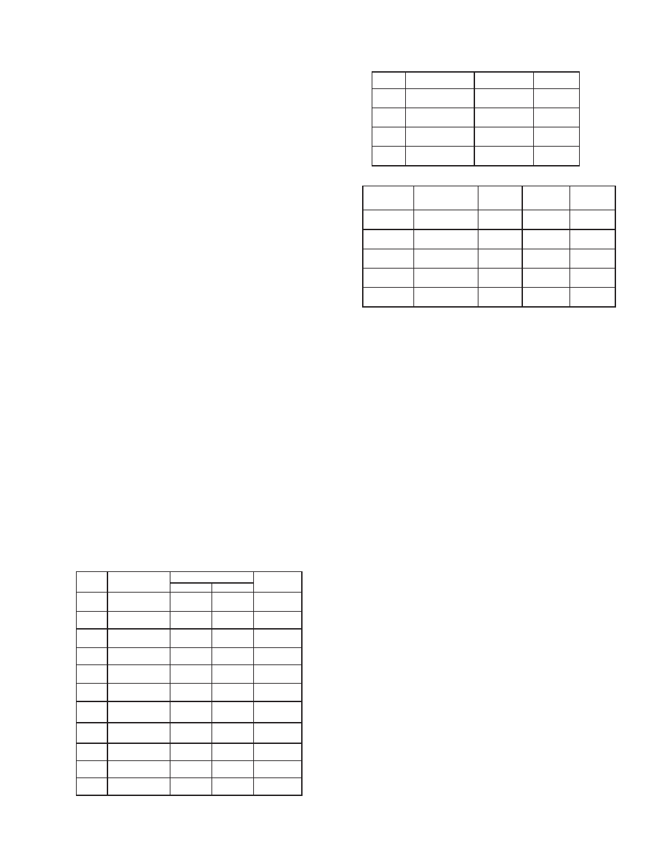
RTD INPUTS:
Type: 2 or 3 wire
Excitation: 180 µA typical
Resolution: 1° or 0.1° for all types
TYPE
INPUT TYPE
RANGE
STANDARD
385
100 Ω platinum,
Alpha = .00385
-200 to +850°C
-328 to +1562°F
IEC 751
392
100 Ω platinum,
Alpha = .003919
-20 to +400°C
-32 to +752°F
No official
standard
672
120
Ω
Nickel
alpha = .00672
-80 to +300°C
-112 to +572°F
Cu50
50
Ω
Copper
alpha = .00428
-50 to +150°C
-58 to +302°F
PROCESS INPUTS:
INPUT RANGE
ACCURACY *
IMPEDANCE
MAX
CONTINUOUS
OVERLOAD
RESOLUTION
0-5 VDC
0.3% of rdg
+ 0.03 V
1.8 M
Ω
50 V
395 µV
0-10 VDC
0.3% of rdg
+ 0.03 V
1.8 M
Ω
50 V
395 µV
0-20 mA
0.3% of rdg
+ 0.04 mA
249
Ω
30 mA
1.6 µA
4-20 mA
0.3% of rdg
+ 0.04 mA
249
Ω
30 mA
1.6 µA
0-50 mV
0.3% of rdg
+ 0.1 mV
4.7 M
Ω
30 V
2.2 µV
*Accuracies are expressed as ± percentages @ 25 °C ambient range after 20
minute warm-up.
7. USER INPUT: (Optional)
Contact Input: ON Resistance 1 KΩ max.
OFF Resistance 100 KΩ min.
Response Time: 1 sec max
Functions: Programmable
8. MEMORY: Nonvolatile E
2
PROM retains all programmable parameters.
9. OUTPUT CAPABILITIES:
Output: Time proportioning or DC Analog
Control: PID, On/Off or user/manual
Cycle Time: Programmable
Auto-Tune: When selected, sets proportional band, integral time, derivative
time, and integration default. Also sets relative gain (if applicable).
Input Fail Action: Programmable output power level
CONTROL RELAY OUTPUTS (OUT1/OUT2):
Type: Form A
Contact Rating: 5 A @ 250 VAC
Life Expectancy: 100,000 cycles at max. load rating
(Decreasing load and/or increasing cycle time, increases life expectancy)
CONTROL SSR DRIVE OUTPUT (OUT1):
Rating: 12 VDC ± 10% @ 40 mA max.
CONTROL ANALOG OUTPUT (OUT1):
Output: Time proportioning or DC Analog
Analog Types: 4 to 20 mA or 0 to 10 VDC
Isolation To Sensor & Communication Common: 500 VDC for 1 min.
Resolution: 12 bit
Compliance: 10 VDC: 1 KΩ load min., 20 mA: 500 Ω load max.
ALARMS: 2 relay alarm outputs.
Type: Form A or Form C, model and alarm dependent
Contact Rating: 3 A @ 250 VAC
Life Expectancy: 100,000 cycles at max. load rating
(Decreasing load and/or increasing cycle time, increases life expectancy)
Modes:
None
Absolute High Acting (Balanced or Unbalanced Hysteresis)
Absolute Low Acting (Balanced or Unbalanced Hysteresis)
Deviation High Acting
Deviation Low Acting
Inside Band Acting
Outside Band Acting
Reset Action: Programmable; automatic or latched
Standby Mode: Programmable; yes or no
Hysteresis: Programmable
Input Fail Response: Programmable
Annunciator: “ALM1”, “ALM2”, and “ALM3”, programmable for
normal or reverse acting