Rogramming, Onfiguration, I c – Red Lion PXU User Manual
Page 11: Configuration loop
11
CONTROL MODE TRANSFER
In Automatic Mode (), the percentage of Output Power is automatically
determined by the controller based on the Auto Control Mode selected. In
Manual/User Mode (), the percentage of Output Power is adjusted
manually by the user. The Control Mode can also be transferred through the 1
or 2 key or User Input. For more information, see Control Mode Explanations.
v
SETPOINT DEVIATION VALUE
Setpoint deviation is the number of display units that the input display varies
from the active setpoint value. This is a read only value.
AUTO-TUNE START
The Auto-Tune procedure sets the Proportional Band, Integral Time,
Derivative Time, Integration Default, and relative Gain (Heat/Cool) values
appropriate to the characteristics of the process. This parameter allows front
panel starting or stopping of Auto-Tune. For more information, see PID
Tuning Explanations.
11
6.0 p
rOgramming
: C
OnfiguraTiOn
l
OOp
2-OP
1-IN
3-LC
4-AL
7-SC
9-FS
no
CNFP
LOOP
HIDDEN
DISPLAY
LOOP
PARAMETERS
INPUT
MODULE
MODULE
OUTPUT
PARAMETERS
LOCKOUT
PARAMETERS
MODULE
COMMUNICATION
PARAMETERS
MODULE
FACTORY
SERVICE
MODULE
ALARM
PARAMETERS
MODULE
P
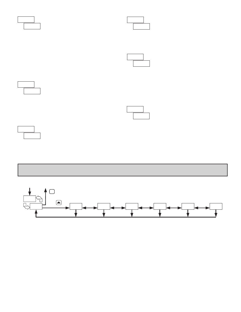
CONFIGURATION LOOP
To access the Configuration Loop, press the up key when C/ is displayed
in the Hidden Loop. In the Configuration Loop, C will alternate with the
parameter number in the bottom display and the Temperature/Process Value is
shown on the top display. The arrow keys are used to select the parameter
module (1-9). To enter a specific module press : while the module number is
displayed. In the Configuration Loop, C will alternate with the parameter
number in the bottom display and the Temperature/Process Value is shown on
the top display.
After entering a parameter module, press : to advance through the
parameters in the module. To change a parameter’s selection/value, press the
arrow keys while the parameter is displayed. In the modules, the top display
shows the parameter name, and the bottom display shows the selection/value.
Use : to enter and store the selection/value that has been changed. If a power
loss occurs before returning to the Display Loop, the new values should be
checked for accuracy.
At the end of each module, the controller returns to C/. At this location,
pressing : again returns the display to the the Display Loop. Pressing the B
key allows re-entrance to the Configuration Loop. Whenever = is pressed,
momentarily appears, the current parameter change will be aborted, and the
controller returns to the Display Loop.
I
C
AUTO CONTROL MODE
PId
or
OnOF
Select the desired control mode. When OnOF is selected, the PID parameters
are not available.
SETPOINT SELECT
or
The
SPSL
function allows the operator to select setpoint 1 or setpoint 2 as the
active setpoint value.
ALARM RESET
This parameter provides for the ability to individually reset active alarms
from the front panel, without using 1 or 2 function keys. When
ALrS
is
displayed with
1-2
on bottom display, pressing the B key, under the 1, will
reset an active Alarm 1. Pressing the J key, under the 2, will reset an active
Alarm 2. When
ALrS
is displayed with 3 on the bottom display, pressing the J
key, under the 3, will reset an active Alarm 3. All alarms may be simultaneously
reset from the front panel by using User 1 or 2 programmed for
ALrS
.
3
s