Pxu p, Rogramming, Uick – Red Lion PXU User Manual
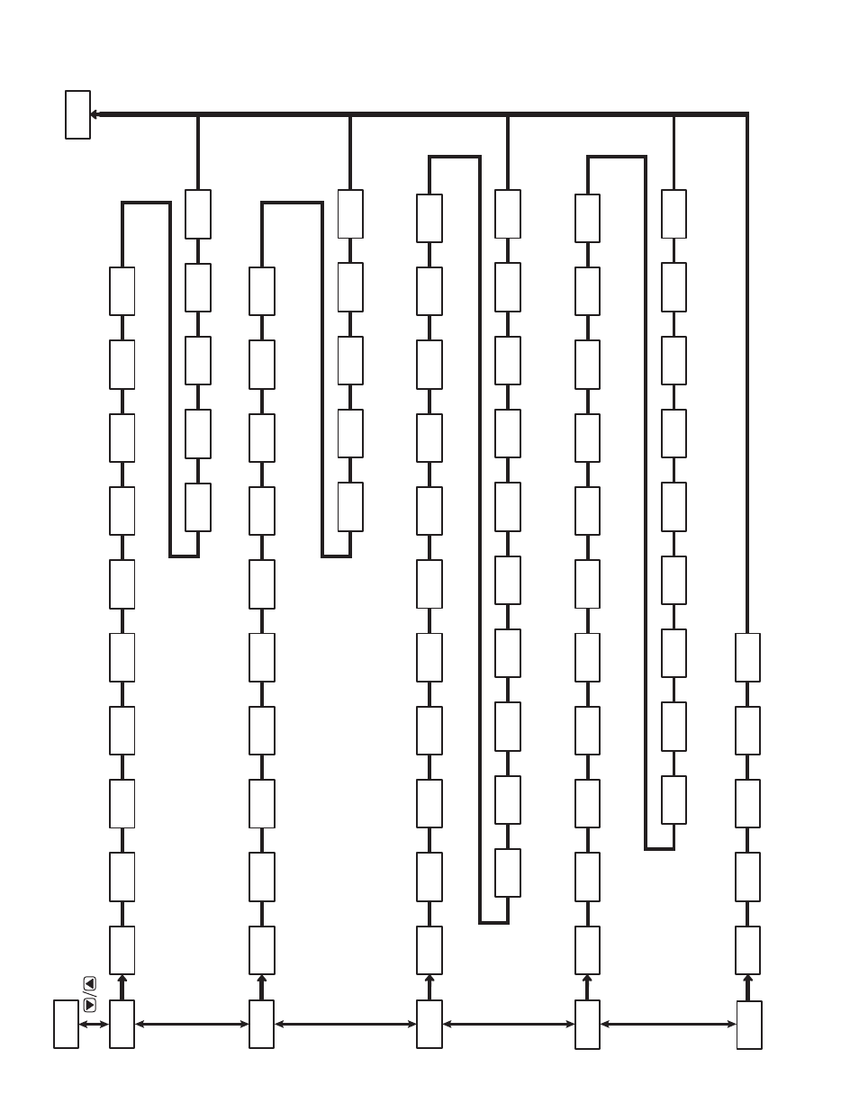
Page 26: Verview, Dcpt, Type, Fltr, Dsp2 band, Shft, Dsp1
26
26
pxu p
rOgramming
Q
uiCK
O
vervieW
1-IN
Decima
l
Resolutio
n
dCPt
Input Ty
pe
tYPE
Digita
l
Filtering
FLtr
Display Value
2
dSP2
bANd
Filte
r
Band
SHFt
Shift/ Of
fset
Display Value
1
dSP1
Setpoint High Limit
SPHI
Setpoint Low Limit
SPLO
Pro
3-LC
4-AL
7-SC
CNFP
2-OP
Te
mp
Scale
SCAL
F1 Ke
y
Function
FIIn
USr1
User Input
1
USr2
User Input
2
Cold
Junction
CJC
F2 Ke
y
Function
F2In
OP1 Cycl
e
Ti
me
CYC1
Contro
l
Actio
n
OPAC
Output
1
Powe
r
Low Limi
t
OP1L
Output
1
Analog High
Scaling
An1H
OP1H
Output
1
Power
High Limi
t
1FO1
Input
Fail OP
1
Power Level
Output
1
Analog Low
Scaling
An1L
Output
2
Gain
gAN2
OP2 Cycl
e
Ti
me
CYC2
Auto Contro
l
Mode
CtrL
Output
2
Powe
r
High Limit
OP2H
db-2
Output
2
Deadband
Output
2
Powe
r
Low Limit
OP2L
On/Of
f
Contro
l
Hysteresi
s
CHYS
Input
Fail OP
2
Power Level
IF02
Output
2
Powe
r
OP2
Setpoint
SP
Setpoint
Ramp Rat
e
SPrP
Proportional
Band
ProP
PId
PID Va
lu
e
r-S
Controlle
r
Status
Output
Power Of
fset
OPOF
Derivativ
e
Ti
me
dErt
Integral Ti
me
Intt
Output
1
Powe
r
OP1
Integration
Default
dInt
Contro
l
Mode Transfe
r
trnF
tUNE
Auto-T
une
Code
Auto Contro
l
Mode
CtrL
Access Code
CodE
Deviation
Value
dEv
Alarm
3
Value
AL-3
AL-1
Alarm
1
Va
lu
e
Alarm
2
Value
AL-2
Setpoint Selec
t
SPSL
Alar
m
Rese
t
ALrS
Alarm
1
Reset Mode
rSt1
Alarm
1
Actio
n
ACt1
Alarm
1
Standby
Stb1
Alarm
2
Annunciator
Lit2
AL-1
Alarm
1
Va
lu
e
IFA1
Input Fail Alarm
1
Action
Alarm
2
Action
ACt2
Alarm
2
Standby
Stb2
Alarm
2
Reset Mode
rSt2
Alarm
1
Annunciato
r
Lit1
Data Bi
t
dAtA
Communications
Ty
pe
tYPE
Parity Bi
t
PArb
Addr
Mete
r
Addres
s
Baud Rate
bAUd
Alarm
2
Value
AL-2
Input Fail Alarm
3
Action
IFA3
Stb3
Alarm
3
Standby
Alarm
3
Value
AL-3
Change Display Color
Colr
Alar
m
Hysteresi
s
AHYS
Alarm
3
Action
ACt3
Input Fail Alarm
2
Action
IFA2
Alarm
3
Reset Mode
rSt3
Alarm
3
Annunciator
Lit3