3 module 3 - d, Isplay, Ront – Red Lion PAXLT User Manual
Page 8: Anel, Arameters
This parameter sets the display update time in seconds.
DISPLAY UPDATE TIME
5.3 Module 3 - d
isplay
and
F
ront
p
anel
K
ey
p
araMeters
(
)
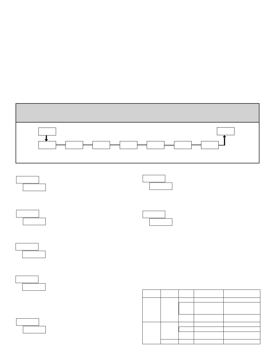
PAR
Pro
Front Panel
Display
Select Enable
Display
Update Time
Front Panel
Reset Enable
Programming
Security Code
3-dSP
dSP-t
SEL
rSt
CodE
Display
Intensity
Level
d-LEV
ScroL
Display
Scroll
Enable
b-LIt
Units Label
Backlight
PARAMETER MENU
This selection allows the
RST button to reset the selected value(s).
FRONT PANEL RESET ENABLE (RST)
The
selection allows the display to automatically scroll through the
enabled displays. The scroll rate is every 4 seconds. This parameter only appears
when the MAX or MIN displays are enabled.
DISPLAY SCROLL ENABLE
Enter the desired Display Intensity Level (1-5). The display will actively dim
or brighten as levels are changed.
DISPLAY INTENSITY LEVEL
The Security Code determines the programming mode and the accessibility
of programming parameters. This code can be used along with the Program
Mode Lock-out (
) in the User Input Function parameter (Module 1).
Two programming modes are available. Full Programming mode allows all
parameters to be viewed and modified. Quick Programming mode permits only
user selected values to be modified, but allows direct access to these values
without having to enter Full Programming mode.
Entering a Security Code from 1-99 enables Quick Programming mode, and
displays a sublist to select which values appear in the Quick Programming
menu. Values set to
in the sublist are accessible in Quick Programming.
These values include the Setpoints (
,
) and Display Intensity (
).
Programming any Security Code other than 0, requires this code to be entered
at the
prompt in order to access Full Programming mode. Quick
Programming mode, if enabled, is accessed before the
prompt appears.
PROGRAMMING SECURITY CODE
to
to
USER INPUT
FUNCTION
USER INPUT
STATE
SECURITY
CODE
MODE WHEN “PAR”
BUTTON IS PRESSED
FULL PROGRAMMING
MODE ACCESS
0
Full Programming
Immediate Access
not
______
1-99
Quick Programming
After Quick Programming
with correct code entry
at
prompt *
100-999
prompt
With correct code entry
at
prompt *
0
Programming Lock
No Access
Active
1-99
Quick Programming
No Access
100-999
prompt
With correct code entry
at
prompt *
Not Active
0-999
Full Programming
Immediate Access
* Entering Code 222 allows access regardless of security code.
8
THERMOCOUPLE Voltage Calibration
1. Connect a precision DC voltage source with an accuracy of 0.01% or better
to the TC and COMM terminals. Set the voltage source to zero.
2. With the display at
, press the
PAR key. Unit displays
.
3. Press
SEL until the display reads
to select thermocouple input.
4. Press
PAR. Display reads
.
5. With the voltage source set to zero, press
PAR. Display reads
for about
6 seconds.
6. When the display reads
, set the voltage source output to 60.000 mV.
Press
PAR. Display reads
for about 6 seconds.
7. When display reads
, press
PAR twice to exit calibration and return to
the normal display mode. Proceed to Cold Junction Calibration.
THERMOCOUPLE Cold Junction Calibration
1. The ambient temperature must be between 20°C and 30°C.
2. Connect a thermocouple (types T, E, J, K or N only) with an accuracy of 1°C
or better to the meter.
3. Enter programming mode and verify the following settings in Module 1:
= thermocouple type connected to the meter
=
;
=
;
=
;
=
4. Place the thermocouple in close thermal contact to a reference thermometer
probe. (Use a reference thermometer with an accuracy of 0.25°C or better.)
The two probes should be shielded from air movement and allowed sufficient
time to equalize in temperature. (A calibration bath of known temperature
could be used in place of the thermometer.)
5. Compare the unit display with the reference temperature indicator (or
calibration bath). If a difference of more than +/- 1.0°C exists, note the
difference (CJ Error) and continue with cold junction calibration.
CJ Error = Reference Temperature - Unit Display
6. Enter programming mode and proceed through Module 2 to the Service
Access Code. Select
and press
PAR. Unit displays
. Press
RST to select
.
7. Press
PAR. Display reads
followed by the current cold junction value.
Calculate a new cold junction value as follows:
New cold junction = Current cold junction + CJ Error (noted above)
8. Press
PAR and set the display to the new cold junction value. Press PAR to
enter the new value. Display reads
for 6 seconds and returns to
.
9. Press
PAR twice to exit calibration and return to the normal display mode.
Verify the input reading is correct. If not, repeat steps 5 through 9.
The
selection allows the
SEL key to toggle through the enabled displays.
FRONT PANEL DISPLAY SELECT ENABLE (SEL)
The PAXLT includes two units overlay labels (°C and °F) which can be
installed into the meter's bezel display assembly. The backlight for the units
label is activated by this parameter.
UNITS LABEL BACKLIGHT
seconds