1 module 1 - i, Nput, Etup – Red Lion PAXLT User Manual
Page 6: Arameters
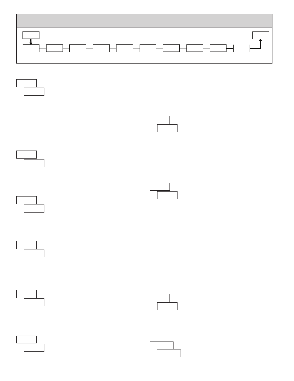
Cold Junction
Compensation
Temperature
Scale
Display
Decimal Point
Filter Setting
User Input
Active Level
Input
Type
PAR
tYPE
CJC
SCALE
dECPt
OFSEt
FILtr
bANd
U-Act
1-INP
Pro
User Input
Function
Display Offset
Value
USrIN
Filter Band
User Input
Assignment
U-ASN
5.1 Module 1 - i
nput
s
etup
p
araMeters
(
)
PARAMETER MENU
6
USER INPUT ACTIVE LEVEL
Select whether the user input is configured as active low or active high.
INPUT TYPE
DISPLAY DECIMAL POINT
Set the decimal point for the desired display resolution. This selection applies
for the Input, MAX and MIN displays, and also affects the Setpoint and Display
Offset values. For mV or RTD resistance displays, the decimal point location is
fixed and this parameter does not appear.
FILTER SETTING
If the displayed temperature is difficult to read due to small process
variations or noise, increased levels of filtering will help to stabilize the display.
FILTER BAND
The filter will adapt to variations in the input signal. When the variation
exceeds the input filter band value, the filter disengages. When the variation
becomes less than the band value, the filter engages again. This allows for a
stable readout, but permits the display to settle rapidly after a large process
change. The value of the band is in display units, independent of the Display
Decimal Point position. A band setting of ‘0’ keeps the filter permanently
engaged at the filter level selected above.
to
display units
Select the thermocouple or RTD type used for the application. For RTDs,
position the Input Range Jumper to match the RTD type (10Ω or 100Ω).
Selecting
displays a millivolt signal readout with 10 µV resolution.
TEMPERATURE SCALE
Select the desired temperature scale. This selection applies for the Input,
MAX and MIN displays. This parameter does not appear when mV or RTD
resistance display is enabled.
DISPLAY OFFSET VALUE
The temperature display can be corrected with an offset value. This can be
used to compensate for probe errors, errors due to variances in probe placement
or adjusting the readout to a reference thermometer.
to
This parameter enables or disables internal cold junction compensation for
thermocouples. For most applications, cold junction compensation should be
enabled (
). This parameter only appears for thermocouple input selections.
COLD JUNCTION COMPENSATION
USER INPUT FUNCTION
Select the value(s) to which the User Input Function is assigned. The User
Input Assignment only applies if a selection of reset or display hold is selected
in the User Input Function menu.
USER INPUT ASSIGNMENT
Software filtering effectively combines a fraction of the current input reading
with a fraction of the previous displayed reading to generate the new display.
Filter values represent no filtering (0), up to heavy filtering (3). A value of 1
for the filter uses 1/4 of the new input and 3/4 of the previous display to
generate the new display. A filter value of 2 uses 1/8 new and 7/8 previous. A
filter value of 3 uses 1/16 new and 15/16 previous.
MODE
Reset *
Program Mode Lock-out
No Function
DESCRIPTION
DISPLAY
Display Select *
Advance once for each activation.
Setpoint 1 and 2 Reset *
Setpoint 2 Reset *
Setpoint 1 Reset *
Reset both setpoint 1 and 2 outputs.
Reset setpoint 2 output.
Reset setpoint 1 output.
Display Intensity Level *
Increase intensity one level for each
activation.
Display Hold
Holds the assigned display, but all other
meter functions continue as long as
activated (maintained action).
Reset the assigned value(s) to the
current input value.
See Programming Mode Access chart
(Module 3).
User Input disabled.
T
E
J
N
C
K
mV
Platinum 385 100 Ω
SELECTION INPUT TYPE
INPUT TYPE
SELECTION
B
S
R
Copper 427 10 Ω
Nickel 672 100 Ω
Platinum 392 100 Ω
* Indicates Edge Triggered function. All others are Level Active functions.