3 user input wiring, 4 setpoint (output) wiring, 2 input signal wiring 3.1 power wiring – Red Lion PAXLT User Manual
Page 4
4
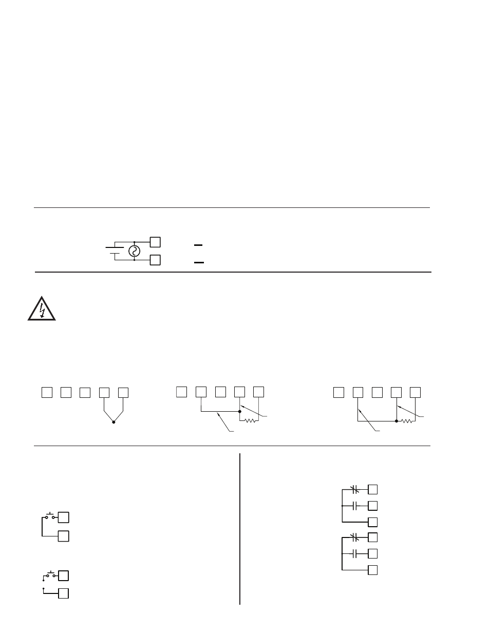
3.3 USER INPUT WIRING
CAUTION: Sensor input common (Terminal 7) is NOT isolated from user common (Terminal 9). In order to preserve the safety
of the meter application, the sensor input common must be suitably isolated from hazardous live earth referenced voltages;
or input common and user common must be at protective earth ground potential. If not, hazardous live voltage may be
present at the user input and user common terminals. Appropriate considerations must then be given to the potential of the
sensor input common and the user common with respect to earth ground.
Terminal 8: User Input
Terminal 9: User Common
3.4 SETPOINT (OUTPUT) WIRING
Terminal 10: NC 1
Terminal 11: NO 1
Terminal 12: Relay 1 Common
Terminal 13: NC 2
Terminal 14: NO 2
Terminal 15: Relay 2 Common
USER INPUT
8
USER COMMON
9
USER INPUT
USER COMMMON
9
8
+
-
10 N.C. 1
COMM 1
12
11 N.O. 1
13
14
15
N.C. 2
N.O. 2
COMM 2
Current Sinking (Active Low Logic)
Current Sourcing (Active High Logic)
3.2 INPUT SIGNAL WIRING
3.1 POWER WIRING
Power
Terminal 1: VAC/DC +
Terminal 2: VAC/DC -
1
2
AC/DC
AC/DC
+
-
~
~
5
+
-
COMM
TC
6
7
RT
D
4
N/
C
3
N/
C
THERMOCOUPLE
Sense Lead
Jumper
RT
D
4
TC
5
6
COMM
7
N/
C
3
N/
C
2-WIRE RTD
RTD (Excitation)
Sense Lead
RT
D
4
TC
5
6
COMM
7
N/
C
3
N/
C
3-WIRE RTD
a. Connect the shield to earth ground (protective earth) at one end where the
unit is mounted.
b. Connect the shield to earth ground at both ends of the cable, usually when
the noise source frequency is over 1 MHz.
3. Never run Signal or Control cables in the same conduit or raceway with AC
power lines, conductors, feeding motors, solenoids, SCR controls, and
heaters, etc. The cables should be run through metal conduit that is properly
grounded. This is especially useful in applications where cable runs are long
and portable two-way radios are used in close proximity or if the installation
is near a commercial radio transmitter. Also, Signal or Control cables within
an enclosure should be routed as far away as possible from contactors, control
relays, transformers, and other noisy components.
4. Long cable runs are more susceptible to EMI pickup than short cable runs.
5. In extremely high EMI environments, the use of external EMI suppression
devices such as Ferrite Suppression Cores for signal and control cables is
effective. The following EMI suppression devices (or equivalent) are
recommended:
Fair-Rite part number 0443167251 (RLC part number FCOR0000)
Line Filters for input power cables:
Schaffner # FN2010-1/07 (Red Lion Controls # LFIL0000)
6. To protect relay contacts that control inductive loads and to minimize radiated
and conducted noise (EMI), some type of contact protection network is
normally installed across the load, the contacts or both. The most effective
location is across the load.
a. Using a snubber, which is a resistor-capacitor (RC) network or metal oxide
varistor (MOV) across an AC inductive load is very effective at reducing
EMI and increasing relay contact life.
b. If a DC inductive load (such as a DC relay coil) is controlled by a transistor
switch, care must be taken not to exceed the breakdown voltage of the
transistor when the load is switched. One of the most effective ways is to
place a diode across the inductive load. Most RLC products with solid state
outputs have internal zener diode protection. However external diode
protection at the load is always a good design practice to limit EMI.
Although the use of a snubber or varistor could be used.
RLC part numbers: Snubber: SNUB0000
Varistor: ILS11500 or ILS23000
7. Care should be taken when connecting input and output devices to the
instrument. When a separate input and output common is provided, they
should not be mixed. Therefore a sensor common should NOT be connected
to an output common. This would cause EMI on the sensitive input common,
which could affect the instrument’s operation.
Visit RLC’s web site at http://www.redlion.net/Support/InstallationConsiderations.
html for more information on EMI guidelines, Safety and CE issues as they
relate to Red Lion Controls products.