2 module 2 - s, Econdary, Unction – Red Lion PAXLT User Manual
Page 7: Arameters
7
5.2 Module 2 - s
econdary
F
unction
p
araMeters
(
)
PAR
Max Capture
Delay Time
Max Display
Enable
Min Display
Enable
Access Code
For Service
Operations
Min Capture
Delay TIme
Factory
Service
Operations
2-SEC
HI-En
HI-t
LO-En
LO-t
FCS
CodE
Pro
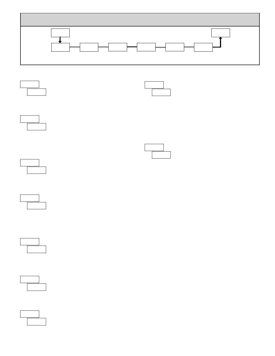
PARAMETER MENU
MIN DISPLAY ENABLE
MIN CAPTURE DELAY TIME
When the Input Display is below the present MIN value for the entered delay
time, the meter will capture that display value as the new MIN reading. A delay
time helps to avoid false captures of sudden short spikes.
to
sec.
Enables the Minimum Display Capture capability.
MAX CAPTURE DELAY TIME
When the Input Display is above the present MAX value for the entered
delay time, the meter will capture that display value as the new MAX reading.
A delay time helps to avoid false captures of sudden short spikes.
to
sec.
MAX DISPLAY ENABLE
Enables the Maximum Display Capture capability.
Entering Code 66 will overwrite all user settings with
the factory settings. The meter will display
and then
return to
. Press the
PAR
button to exit the module
Select
to perform any of the Factory Service Operations shown below.
FACTORY SERVICE OPERATIONS
RESTORE FACTORY DEFAULT SETTINGS
Entering Code 50 will display the version (x.x) of the
meter. The display then returns to
. Press the
PAR
button to exit the module.
VIEW MODEL AND VERSION DISPLAY
Entering Code 85 toggles the selected RTD input display
mode between a temperature or resistance readout. The
resistance readout is useful for diagnostic purposes before
and after calibration, or to display the measured resistance
of a connected RTD probe.
For RTD type
(Input Range Jumper in 10Ω position), resistance is
displayed in
ohms resolution. For all other RTD types (100Ω position),
resistance is displayed in
ohms resolution.
Upon entering Code 85, the meter displays either
or
to indicate
temperature or resistance readout selected. The display then returns to
.
Press the
PAR
button to exit the module.
TOGGLE RTD INPUT DISPLAY MODE
The PAXLT uses stored calibration values to provide
accurate temperature measurements. Over time, the
electrical characteristics of the components inside the
meter could slowly change, with the result being that the
stored calibration values may no longer accurately define
the input circuit. For most applications, recalibration every 1 to 2 years should
be sufficient.
Calibration for thermocouple inputs involves a voltage calibration and a cold
junction calibration. It is recommended that both calibrations be performed. The
voltage calibration must precede cold junction calibration.
Calibration of the meter should only be performed by persons experienced in
calibrating electronic equipment. Allow a minimum 30 minute warm up before
performing any calibration procedures. The following procedures should be
performed at an ambient temperature of 15 to 35°C (59 to 95°F).
CAUTION: The accuracy of the calibration equipment will directly affect the
accuracy of the meter.
10 OHM RTD Range Calibration
1. Set the Input Range Jumper to 10 ohm position.
2. With the display at
, press the
PAR key. Unit displays
.
3. Press
SEL to select 10 ohm range. Display reads
.
4. Press
PAR. Display reads
.
5. Apply a direct short to terminals RTD (4), TC (6) and COMM (7) using a
three wire link. Press
PAR. Display reads
for about 10 seconds.
6. When the display reads
, apply a precision resistance of 15 ohms (with
an accuracy of 0.01% or better) to terminals RTD, TC and COMM using a
three wire link. Press
PAR. Display reads
for about 10 seconds.
7. When display reads
, press
PAR twice to exit calibration and return to
the normal display mode.
100 OHM RTD Range Calibration
1. Set the Input Range Jumper to 100 ohm position.
2. With the display at
, press the
PAR key. Unit displays
.
3. Press
SEL twice to select 100 ohm range. Display reads
.
4. Press
PAR. Display reads
.
5. Apply a direct short to terminals RTD (4), TC (6) and COMM (7) using a
three wire link. Press
PAR. Display reads
for about 10 seconds.
6. When the display reads
, apply a precision resistance of 300 ohms (with
an accuracy of 0.01% or better) to terminals RTD, TC and COMM using a
three wire link. Press
PAR. Display reads
for about 10 seconds.
7. When display reads
, press
PAR twice to exit calibration and return to
the normal display mode.
CALIBRATION