Vaisala WXT510 User Manual
Page 40
User’s Guide ______________________________________________________________________
38 __________________________________________________________________ M210470EN-D
0505-204
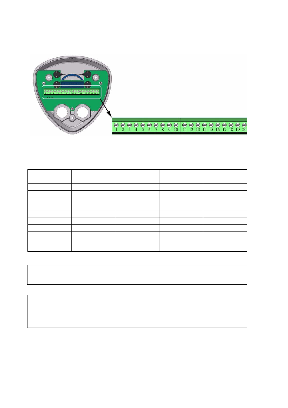
Figure 16
Screw Terminal Block
Table 1
Screw Terminal Pin-outs for WXT510 Serial
Interfaces and Power Supplies
Screw Terminal
Pin
RS-232
SDI-12
RS-485
RS-422
1 RX-
-
-
Data-
Data in (RX-)
2 RX+
-
-
Data+
Data in (RX+)
3 TX-
Data out (TxD)
Data in/out (Tx)
Data-
Data out (TX-)
4 TX+
-
-
Data+
Data out (TX+)
5 RXD
Data in (RxD)
Data in/out (Rx)
-
-
6 SGND
GND for data
GND for data
-
-
17 HTG-
GND for Vh+
GND for Vh+
GND for Vh+
GND for Vh+
18 HTG+
Vh+ (heating)
Vh+ (heating)
Vh+ (heating)
Vh+ (heating)
19 VIN-
GND for Vin+
GND for Vin+
GND for Vin+
GND for Vin+
20 VIN+
Vin+ (operating)
Vin+ (operating)
Vin+ (operating)
Vin+ (operating)
NOTE
In the true SDI-12 mode the two Data in/out lines must be combined
either in the screw terminal or outside WXT510.
NOTE
Short-circuit jumpers are required between pins 1-3 and 2-4 for the
RS-485 communication mode. For the RS-422 mode, the jumpers
should be removed. In the other modes the jumpers may stay or they
can be removed.