Vaisala WXT510 User Manual
Page 21
Chapter 2 __________________________________________________________ Product Overview
VAISALA _______________________________________________________________________ 19
0505-193
Figure 5
Mounting Kit (Optional)
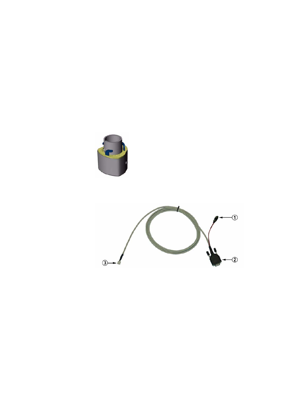
0505-194
Figure 6
Service Cable (Optional)
The following numbers refer to
Figure 4 on page 18
:
1
=
Alignment direction sign
2
=
Service port
3
=
Water tight cable gland (shown disassembled)
4
=
Opening for cable gland (if unused, cover with hexagonal
plug)
5
=
8-pin M12 connector for power/datacom cable (optional,
cover with hexagonal plug if unused)