I2c interface, Overview, Physical interface – Vaisala GMP231 User Manual
Page 52: Chapter 5, C interface, Figure 12, Hardware schematic, Chapter 5, i2c interface
User's Guide _______________________________________________________________________
50 ___________________________________________________________________ M211501EN-C
CHAPTER 5
I
2
C INTERFACE
This chapter describes the I
2
C interface implementation of the GMP231.
Overview
GMP231 has an inter-integrated circuit (I
2
C) interface for interfacing
with the incubator’s control computer. GMP231 implements I
2
C slave
functionality, with the incubator’s computer acting as the master. The
interface can be used to read measurement values and status information,
set operation parameters, and make adjustments.
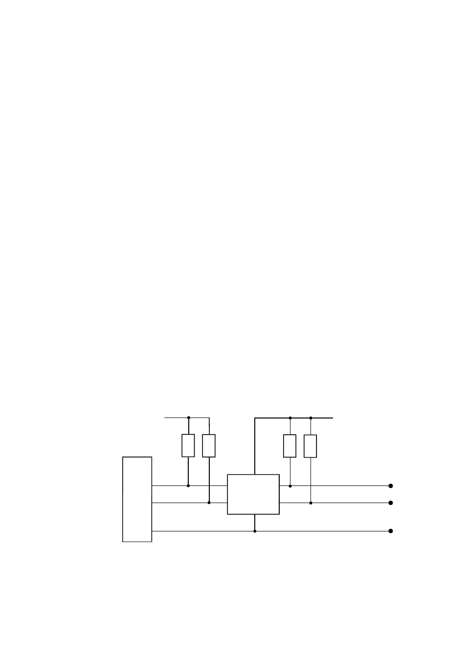
Physical Interface
The physical interface is a non-isolated 3-wire interface. Wires are SDA,
SCL and ground. SDA and SCL lines are buffered. Ground is shared
with power supply. There are small pull-up resistors for SCL and SDA.
Connector is 8 pin male M12. Maximum cable length should not exceed
5 m and maximum capacitance between communication lines and ground
should not exceed 500 pF.
For connector pinout and wiring information, see section Wiring on page
24.
1403-149
Figure 12
Hardware Schematic
3.3 V
5.0 V
SDA
SCL
GND
2 x 10 kΩ
2 x 10 kΩ
uP
Buffer and
level shift