Recommended installation, Figure 10 – Vaisala GMP231 User Manual
Page 25
Chapter 3 ________________________________________________________________ Installation
VAISALA ________________________________________________________________________ 23
Recommended Installation
GMP231 is designed to be installed through a chamber wall, and attached
to the chamber chassis using an attachment bracket and the two screw
holes on the side of the probe. As the installation depth of the probe
inside the chamber is critical (see section Probe Installation Depth on
page 21), the mounting method must allow the probe to be positioned
exactly.
NOTE
The probe and electronics housing must remain outside the heated
chamber. The electronics housing should be in a ventilated space that is
open to ambient air.
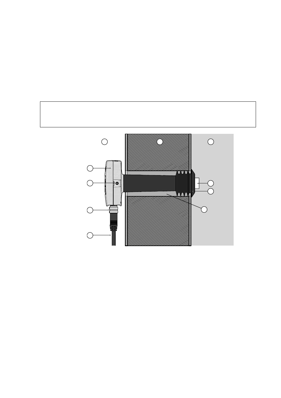
1403-123
Figure 10
Recommended Installation
1 = Ambient air.
2 = Chamber wall.
3 = Chamber interior.
4 = GMP231 Electronics housing.
5 = M4 screw holes on both sides of the probe housing.
6 = 8-pin M12 connector. For pinout, see section Wiring on page 24.
7 = Cable.
8 = CARBOCAP
®
sensor under PTFE filter. The filter must be inside
the chamber completely.
9 = Silicone plug. Insert the plug over the probe from inside the
chamber.
10 = Ø 44 mm installation tube through the chamber wall.
The diameter is important for proper sealing by the silicone plug.
4
1
2
3
5
6
7
9
8
10