Wiring, Power supply, Table 4 – Vaisala GMP231 User Manual
Page 26: Gmp231 connector pinout, Table 5, Cable drw240977
User's Guide _______________________________________________________________________
24 ___________________________________________________________________ M211501EN-C
Wiring
GMP231 provides several outputs you can use. Connect the output pins
you need, and the power supply and ground pins. Use a shielded cable,
and connect the shield to the chassis of the GMP231’s M12 connector,
and to ground on the other side.
Ground pin 5 to put the probe in standby mode (stops CO
2
measurement).
The probe resumes normal measurement operation when pin 5 is no
longer grounded, unless its internal measurement shows the temperature
is too high.
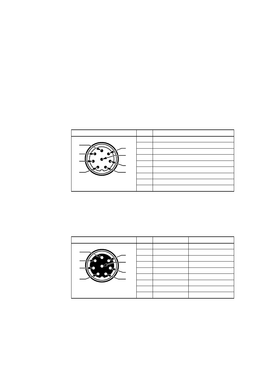
Table 4
GMP231 Connector Pinout
Male 8-pin M12
Pin # Function
1
I
2
C SDA
2
RS-485 D-
3
I
2
C SCL
4
Analog output +
5
Standby
6
RS-485 D+
7
Power supply +
8
Ground
-
Shield
Vaisala’s standard connection cable for the GMP231 (order code
DRW240977) is a 90 cm long cable with female 8-pin M12 connector on
one end, and open ended wires on the other. It supports all outputs from
the GMP231, and connects the cable shield to the connector chassis.
Table 5
Cable DRW240977
Female 8-pin M12
Pin # Function
Wire Color
1
I
2
C SDA
White
2
RS-485 D-
Brown
3
I
2
C SCL
Green
4
Analog output + Yellow
5
Standby
Gray
6
RS-485 D+
Pink
7
Power supply + Blue
8
Ground
Red
-
Shield
Black
Power Supply
The supply voltage range of the GMP231 is 11 ... 30 VDC.
If the analog output is used, the supply voltage range is 20 ... 30 VDC.
The maximum power consumption is 1 W.
1
5
6
7
3
4
8
2
1
6
8
7
3
4
5
2