Junction board connections, Procedure 3. mount the new temp/hum module – DAVIS Vantage Pro ISS Retrofit Kit for Fan-Aspirated Station User Manual
Page 5
Installation Outline
Page 5
2.
The SIM transmitter board, dust cover, and rear cover plate (not shown) are
attached to the top radiation shield plate using 4 screws. Unfasten these
screws and remove the dust cover along with the board and mounting
plate.
3.
Remove the SIM power cable, solar panel cable and the Sensor Interface
Cable from the junction board located in the lower section of the radiation
shield.
Procedure 3. Mount the New Temp/Hum Module
1.
Remove the fan and fan deflector from the lower section of the radiation
shield.
2.
Remove the old Temp/Hum module from the radiation shield and unplug
it from the junction board.
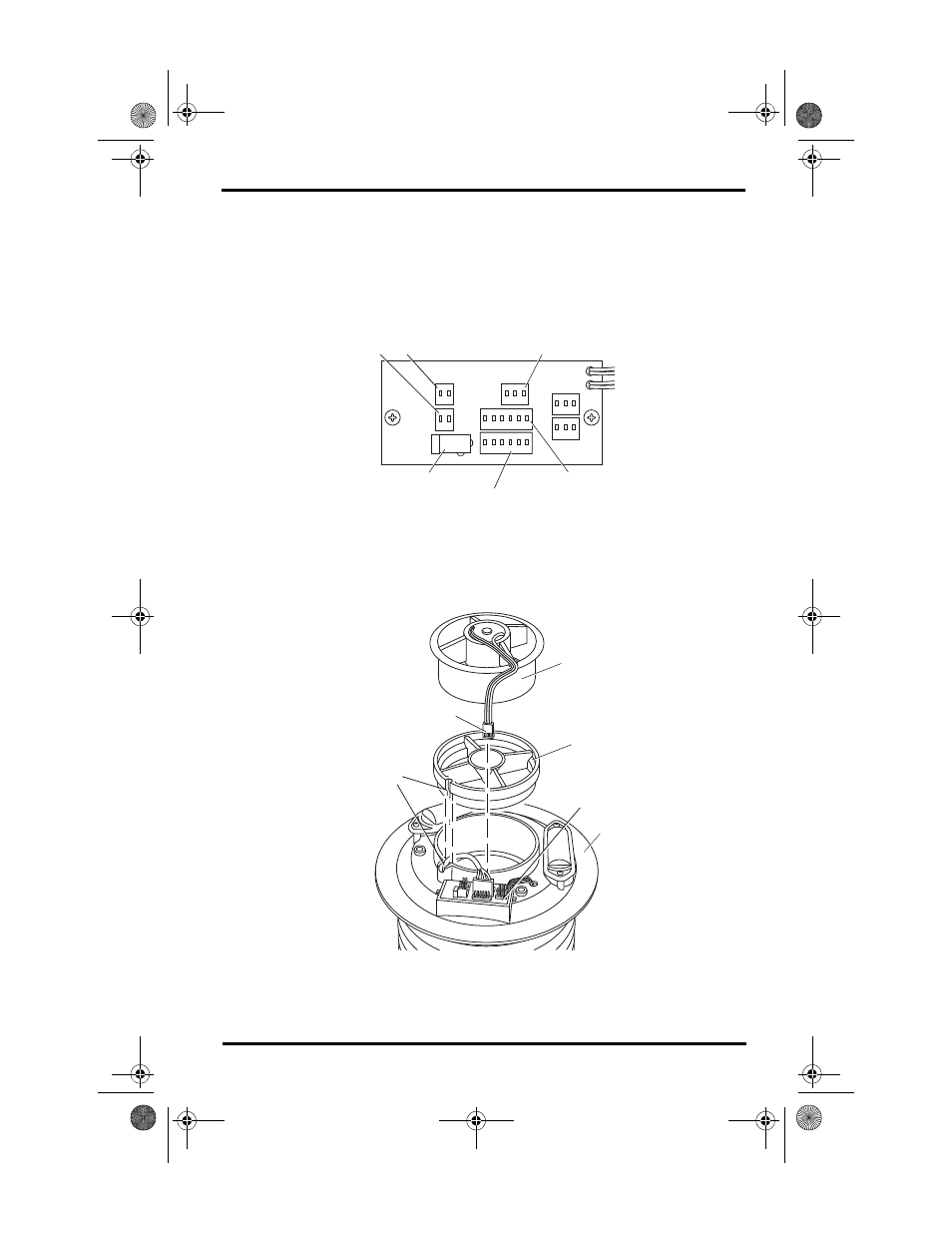
+VSIM
MOTOR
+VSIM
+VSOL
+5V
T/H & SIM
TACH
Solar and SIM Power Connectors
(Wireless ISS Only)
Fan Connector
AC Power Adapter Connector
(Cabled ISS Only)
Temp/Hum Sensor
Connector
Sensor Interface
Connector
Junction Board Connections
Fan Unit
Fan Deflector
Motor Connector
Junction Board
Temp/Hum
Sensor Cable
Channel
Fan Plate
ISS2 SPARS RetroKit D011.fm Page 5 Wednesday, April 23, 2003 11:26 AM
- Envoy8X Getting Started Guide (16 pages)
- Vantage Pro2 Long Range Repeater Installation Addendum (16 pages)
- Wireless Temperature Station (6372) Installation Manual (12 pages)
- Solar Power Kit For Vantage Weather Stations and Envoy8X (8 pages)
- Energy EnviroMonitor: Console (63 pages)
- EZ-Mount Installation (16 pages)
- Gro/Energy/Health Installation (24 pages)
- GroWeather Console (65 pages)
- GroWeather/EnviroMonitor: Systems Installation (24 pages)
- Health EnviroMonitor: Console (60 pages)
- Anemometer (7911, 7914) (8 pages)
- Rain Collector II for GroWeather, EnviroMonitor, Weather Monitor and Wizard (16 pages)
- Sensor - UV for GroWeather or EnviroMonitor (16 pages)
- Solar Radiation Sensor for GroWeather and EnviroMonitor (16 pages)
- Temperatur/Humidity Sensor for GroWeather, EnviroMonitor, & Weather Monitor (12 pages)
- Temperature Sensor/Probe for GroWeather, EnviroMon., Weather Monitor/Wizard (4 pages)
- GroWeatherLink Software (108 pages)
- GroWeatherLink/ET Data Logger (2 pages)
- Short-Range Modem Pair: Perception, GroWeather, EnviroMon., Monitor, Wizard (8 pages)
- Alarm Output Module (16 pages)
- Cable Coupler Kit (4 pages)
- Cable Crimp-Type Splice Connector (4 pages)
- Complete System Shelter (12 pages)
- Fan-Aspirated Radiation Shield (24 pages)
- Grounding Kit (4 pages)
- Interface Cable Adapter Module (8 pages)
- Mounting Pole Kit Installation (4 pages)
- Mounting Tripod Kit (8 pages)
- Multi-purpose Shelter (12 pages)
- Radiation Shield (7714) (16 pages)
- Radio Surge Protector (4 pages)
- Rain Collector Heater (12 pages)
- Rain Collector Shelf: GroWeather, EnviroMonitor, Weather Monitor & Wizard (8 pages)
- Second Solar Panel for EZ-Mount Solar Power Kit (4 pages)
- Sensor Mounting Arm for GroWeather, EnviroMonitor, Weather Monitor & Wizard (16 pages)
- Sensor Tilting Bracket for GroWeather or EnviroMonitor (8 pages)
- Shelter Heaters (12 pages)
- Solar Power Kit for Non-Vantage Pro Stations (16 pages)
- Surge Protector (2 pages)
- Surge Protector Shelter - Large (8 pages)
- Surge Protector Shelter - Small (4 pages)
- Terminal Box for sensors/interface module, communication lines: GroWeather (8 pages)
- WeatherLink for Windows 4.0 (116 pages)
- WeatherLink Getting Started Guide (20 pages)
- WeatherLink Mac OS X Getting Started Guide (16 pages)