JKS 2943 User Manual
Page 5
JKS2943
JKS Adjustable Sway Bar Links Installation
Page 5
Using the value provided by the formula above,
mark each end of the Connecting Rod (A) to
indicate the appropriate locations to cut.
HINT:
Remove same amount of thread material from
each end.
Using an appropriate cutting tool (such as a die
grinder with cutting wheel, or metal cutting saw),
carefully and squarely cut each end of the Con-
necting Rod (A) where previously marked.
Now completely unthread both 1/2” Jam Nuts (C)
from Connecting Rod (A) and re-install. HINT: This
will help to repair any thread damage that may
have occurred during the cutting process.
Apply a drop of medium strength thread locking
compound to the tip of threads at each end of
Connecting Rod (A).
Completely thread a Rod End (B) on to each end
of Connecting Rod.
4. INSTALL END LINKS
If you are installing this product on a Rubicon
model with electronic front swaybar disconnect,
you must now enlarge the mounting holes on the
swaybar using a 17/32” drill bit.
Using the supplied 1/2” Flanged Locking Nuts (D),
secure the Adjustable End Links to the swaybar
and axle bracket. Make sure upper and lower Rod
Ends (B) are in alignment with their respective
mounting surfaces.
IMPORTANT: End Links must be installed on
outboard side of swaybar and inboard side of axle
bracket.
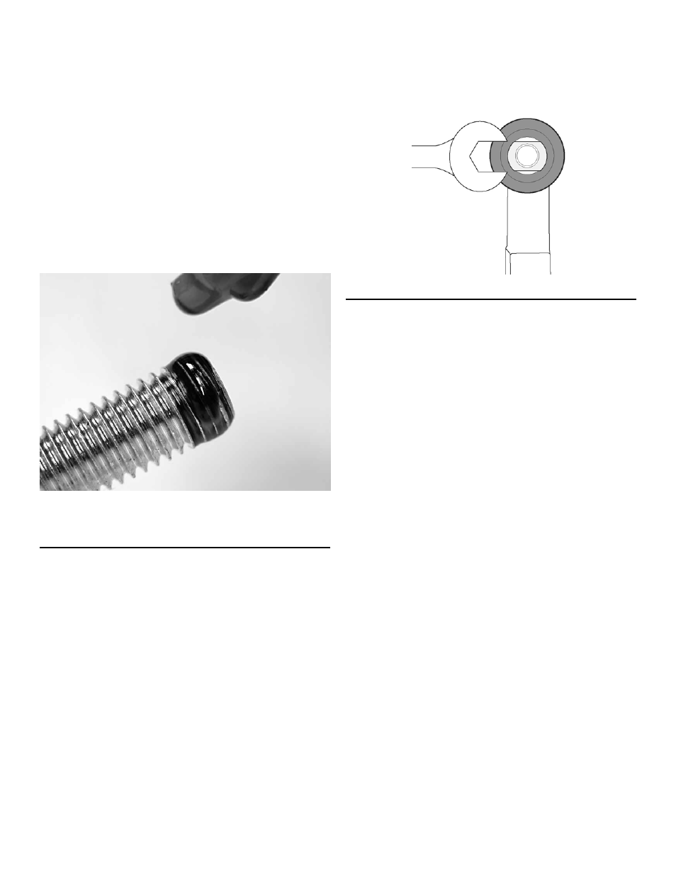
Once all adjustments are complete, fully tighten
the Jam Nuts (C) against the Rod Ends (B) to pre-
vent length of Adjustable End Links from changing.
Tighten the 1/2” Flanged Locking Nuts (D) to 40
ft-lbs. using a torque wrench.
HINT: Use flat spot on Rod Ends (B) to prevent
mounting stud from spinning when tightening 1/2”
Flanged Locking Nut (D).
©2013 JKS Manufacturing, Inc & Aftermarketing, LLC
Revision Date 9/30/2013