Parts, Installation – JKS 2943 User Manual
Page 2
JKS2943
JKS Adjustable Sway Bar Links Installation
2 Page
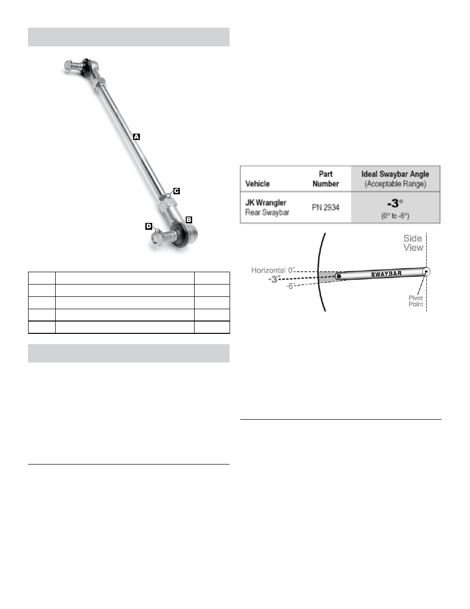
Parts
Description
QTY
A
Connecting Rod
2
B
Rod End
4
C
1/2” Jam Nut
4
D
1/2” Flanged Locking Nut
4
Installation
1. REMOVE ORIGINAL EQUIPMENT
(OE) REAR SWAYBAR LINKS
Remove the original mounting hardware that
secures the rear swaybar links to the swaybar and
axle.
Discard original rear swaybar links and mounting
hardware.
2. DETERMINE PROPER LENGTH OF
ADJUSTABLE END LINKS
The Adjustable End Links can be adjusted to any
length between 8.75” and 15” (measured from center-
to-center of rod ends). However, it is critically impor-
tant to set the length correctly for your application.
If the End Links are too long, they will contact
the brake lines running along the chassis, which
could lead to complete brake system failure. If
the End Links are too short, they will limit sus-
pension travel at full extension.
Adhere to the following instructions carefully to
ensure that your Adjustable End Links are set to the
correct length.
Rotate the rear swaybar to the Ideal Angle (or
within Acceptable Range) listed below. Vehicle
must be at normal ride height and located on level
ground.
While holding the swaybar at the proper angle,
measure the distance between the center of the
original mounting holes on the swaybar and axle
bracket.
Subtract 2.25” from the distance recorded above
to determine the correct length of the Connecting
Rod (A).
HINT: For instance, if the center-to-center
distance for your application is 10”, the Connecting
Rod length should be 7.75”.
3. MODIFY CONNECTING ROD
Now that you know the correct Connecting Rod
(A) length for your application, subtract the length
from the overall Connecting Rod length of 12.75”
and then divide by 2 to determine the amount of
material to remove from each end.
HINT: For instance, if the correct Connecting Rod
length for your application is 7.75”, the amount
of material to remove from each end will be 2.5”.
Example 12.75 - 7.75 = 5 and 5 ÷ 2 = 2.5”
Remove Rod Ends (B) from both ends of the Con-
necting Rod (A). Do not remove 1/2” Jam Nuts (C).
Using the value provided by the formula above,
mark each end of the Connecting Rod (A) to indi-
cate the appropriate locations to cut.