Front installation – JKS 2943 User Manual
Page 4
JKS2943
JKS Adjustable Sway Bar Links Installation
4 Page
IMPORTANT: It should not be necessary to grind
all the way through the steel bracket. Only re-
move enough material to eliminate the interfer-
ence problem.
Once sufficient clearance has been established,
apply spray paint to any bare metal on control arm
bracket to prevent corrosion.
Reinstall Adjustable End Link on swaybar and
tighten per the instructions earlier in this section.
5. TEST FOR INTERFERENCE
Before driving vehicle, compress the rear suspen-
sion to check for interference between the Adjust-
able End Links and chassis-mounted brake lines.
If any interference occurs, take corrective action
by utilizing one of the following methods:
Add or adjust bump stop height of rear suspension
to prevent upper Rod Ends (B) from contacting
brake lines.
Reduce length of Adjustable End Links by remov-
ing additional thread material from the Connecting
Rod (A). Remove only as much thread material as
necessary to eliminate interference. If Adjustable
End Links are too short, rear suspension travel will
be restricted.
Carefully bend the brake lines inward (toward
chassis) to gain approximately 0.25” of additional
clearance.Front Installation
Front Installation
1. REMOVE ORIGINAL EQUIPMENT
(OE) FRONT SWAYBAR LINKS
Remove the original mounting hardware that
secures the front swaybar links to the swaybar and
axle.
Discard original front swaybar links and mounting
hardware.
2. DETERMINE PROPER LENGTH OF
ADJUSTABLE END LINKS
The Adjustable End Links can be adjusted to any
length between 8.75” and 15” (measured from center-
to-center of rod ends). Adhere to the following instruc-
tions carefully to ensure that your Adjustable End
Links are set to the correct length.
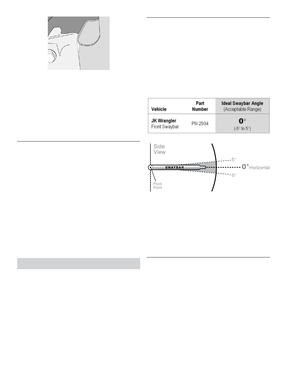
Rotate the front swaybar to the Ideal Angle (or
within Acceptable Range) listed below. Vehicle
must be at normal ride height and located on level
ground.
While holding the swaybar at the proper angle,
measure the distance between the center of the
original mounting holes on the swaybar and axle
bracket.
Subtract 2.25” from the distance recorded above
to determine the correct length of the Connecting
Rod (A).
HINT: For instance, if the center-to-center
distance for your application is 10”, the Connecting
Rod length should be 7.75”.
3. MODIFY CONNECTING ROD
Now that you know the correct Connecting Rod (A)
length for your application, subtract the length from
the overall Connecting Rod length of 12.75” and
then divide by 2 to determine the amount of mate-
rial to remove from each end.
HINT: For instance, if the correct Connecting Rod
length for your application is 7.75”, the amount
of material to remove from each end will be 2.5”.
Example 12.75 - 7.75 = 5 and 5 ÷ 2 = 2.5”
Remove Rod Ends (B) from both ends of the Con-
necting Rod (A). Do not remove 1/2” Jam Nuts (C).