JKS 2943 User Manual
Page 3
JKS2943
JKS Adjustable Sway Bar Links Installation
Page 3
HINT: Remove same amount of thread material
from each end.
Using an appropriate cutting tool (such as a die
grinder with cutting wheel, or metal cutting saw),
carefully and squarely cut each end of the Con-
necting Rod (A) where previously marked.
Now completely unthread both 1/2” Jam Nuts (C)
from Connecting Rod (A) and re-install.
HINT: This
will help to repair any thread damage that may
have occurred during the cutting process.
Apply a drop of medium strength thread locking
compound to the tip of threads at each end of
Connecting Rod (A).
Completely thread a Rod End (B) on to each end
of Connecting Rod.
4. INSTALL END LINKS
Using the supplied 1/2” Flanged Locking Nuts (D),
secure the Adjustable End Links to the swaybar
and axle bracket. Make sure upper and lower Rod
Ends (B) are in alignment with their respective
mounting surfaces.
IMPORTANT: End Links must be installed on out-
board side of swaybar and axle bracket.
Once all adjustments are complete, fully tighten
the Jam Nuts (C) against the Rod Ends (B) to pre-
vent length of Adjustable End Links from changing.
Tighten the 1/2” Flanged Locking Nuts (D) to 40
ft-lbs. using a torque wrench.
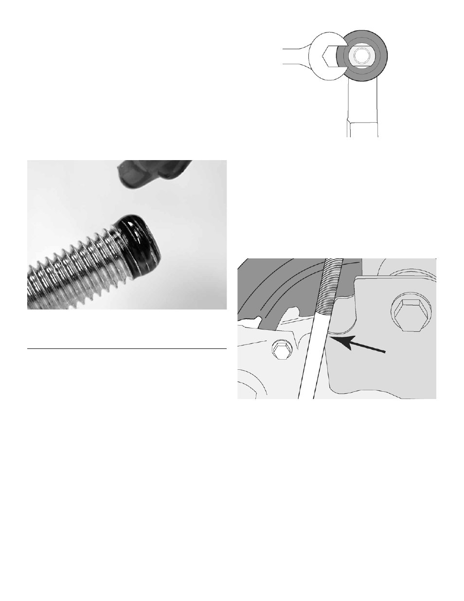
HINT: Use flat spot on Rod Ends (B) to prevent
mounting stud from spinning when tightening 1/2”
Flanged Locking Nut (D).
On the upper Rod Ends (B) only, cut the excess
thread material from the mounting stud so that
none of the threaded portion protrudes beyond
Flanged Locking Nut (D).
On vehicles in which the rear axle housing has been
rotated to correct the pinion angle following a CV
driveshaft installation, there may be insufficient clear-
ance between the upper control arm bracket on the
axle and the Connecting Rod (A).
Check for interference where indicated by the ar-
row in the illustration below.
If interference between the control arm bracket and
Connecting Rod (A) is discovered, it will be necessary
to clearance the bracket per the following instructions.
Locate the area of interference and mark the loca-
tion on both upper control arm brackets.
Temporarily remove the Adjustable End Link from
the swaybar to provide access to the control arm
bracket.
Remove just enough material from the control arm
bracket to prevent the Connecting Rod (A) from
contacting it.
HINT: A die grinder or metal grind-
ing wheel is useful for removing material from the
control arm bracket.