Caution – JKS 2034 User Manual
Page 4
JKS2030 - JKS2034
JKS Quicker Disconect Installation
Page A
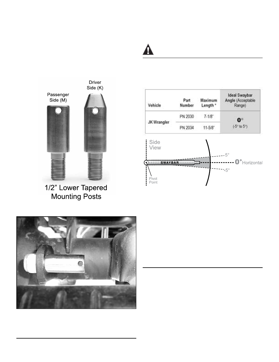
3. INSTALL LOWER MOUNTING POSTS
Insert stainless steel 1/2” Lower Tapered Mount-
ing Posts (K & M) into lower swaybar link holes on
front axle. Position posts with tapered ends point-
ing inboard, ensuring small Click Pin holes are
horizontal or parallel with the ground.
IMPORTANT: The passenger side lower post is
squared off to provide sufficient clearance between
the post and the OE trackbar bracket on the axle.
Apply medium strength threadlocker to the tip of
mounting post threads.
Install 1/2” Nylock Nuts (L) on outboard side of
lower swaybar link brackets and tighten to 65 ft-lb.
using a torque wrench.
4. SET QUICKER DISCONNECT
LENGTHS
Determine the Ideal Swaybar Angle for your ve-
hicle according to the following chart.
CAUTION
Max. length is based on required thread & jam nut engage-
ment. Measure & DO NOT extend Quicker Disconnects™
beyond maximum length of your part number (bushings
center to center).
Adjust the length of your Quicker Disconnects until
swaybar is at the Ideal Angle or within Acceptable
Range. Vehicle must be at normal ride height and
located on level ground.
Once adjusted, lay Quicker Disconnects on a
flat surface and tighten 5/8” Jam Nuts (H) firmly
against the Lower Ends (I).
IMPORTANT: Bushing cradles at both ends of
Quicker Disconnect must remain parallel with
each other when Jam Nut is tightened.