Hydraulic downforce, Cable diagram, Quick reference guide – Ag Leader Versa DirectCommand Hydraulic Down Force Quick Reference Guides User Manual
Page 4
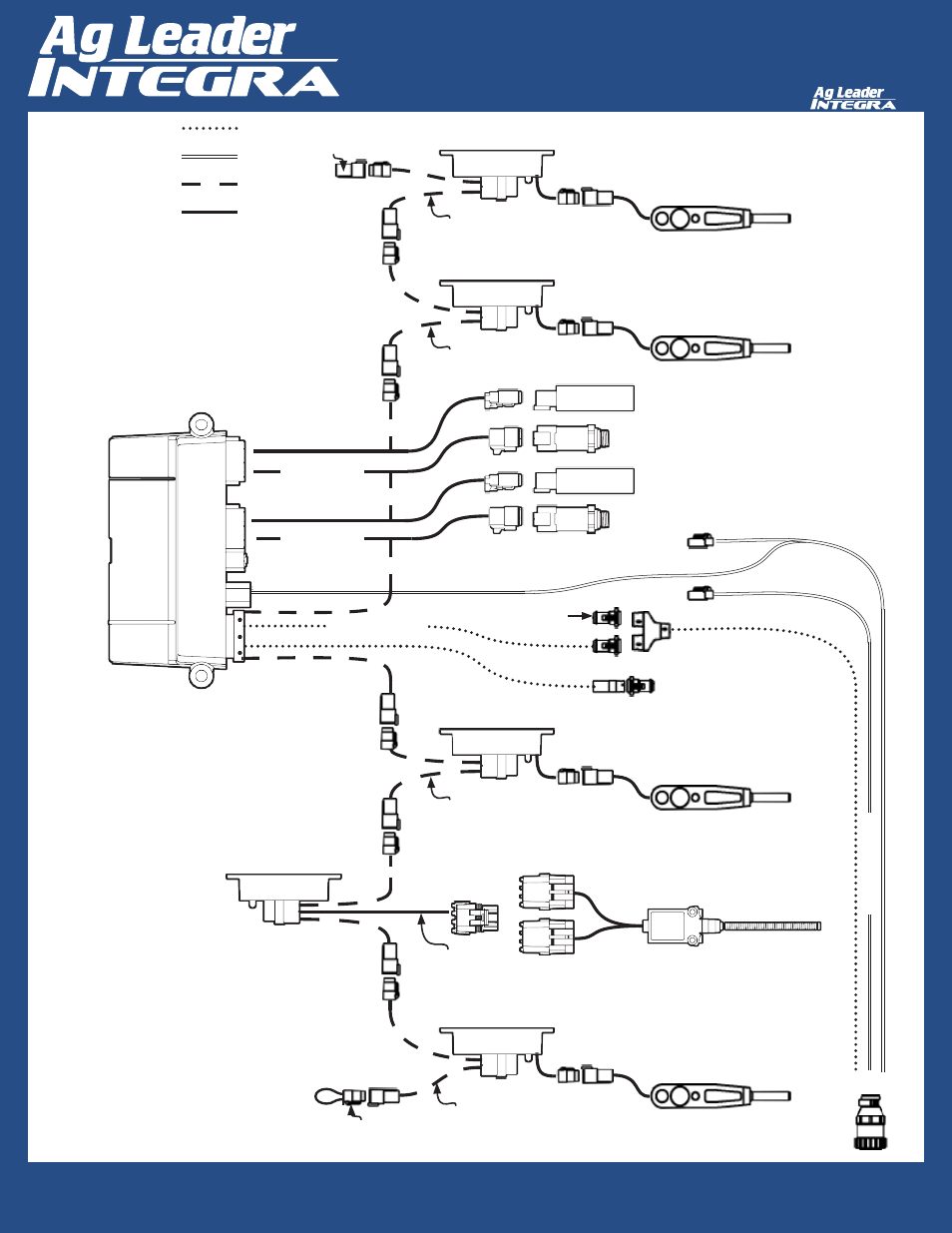
4
Hydraulic Downforce
Quick Reference Guide
AL: 2006350 ENG Rev B
Cable Diagram
Terminator
P/N 4002871
Right End of Planter
At least one implement switch must be installed on the
Seed Command system.
Row Module
P/N 4002912-1
Load Sensor
Row Module
P/N 4002912-1
Load Sensor
Row Module
P/N 4002912-1
Load Sensor
Load Sensor
CAN Implement Switch
P/N 4002911
Implement Switch
Dust Cap
Channel 2 Solenoid Valve
Channel 1 Pressure
Channel 2 Pressure
Channel 1 Solenoid Valve
Row Module Breakout
Row Module Breakout
Row Module Breakout
Row Module Breakout
P/N 4002920-008
Channel Cable
Channel Cable
P/N 4000726-12
Down Force Control Module
Terminator
P/N 4002870
Left End of Planter
Row Module
P/N 4002912-1
CAN A
HIGH POWER
LOCAL CAN BUS
SIGNAL/CONTROL
Terminating
Plug P/N
4002871
must
be installed on
the right end of
the planter.
Terminating Plug P/N 4002870
must be
installed on the left end of the planter.
Control module and Implement Switch module(s) can
be placed anywhere in series on the local CAN Bus.
P/N 4002658