Hydraulic downforce, Quick reference guide – Ag Leader Versa DirectCommand Hydraulic Down Force Quick Reference Guides User Manual
Page 2
2
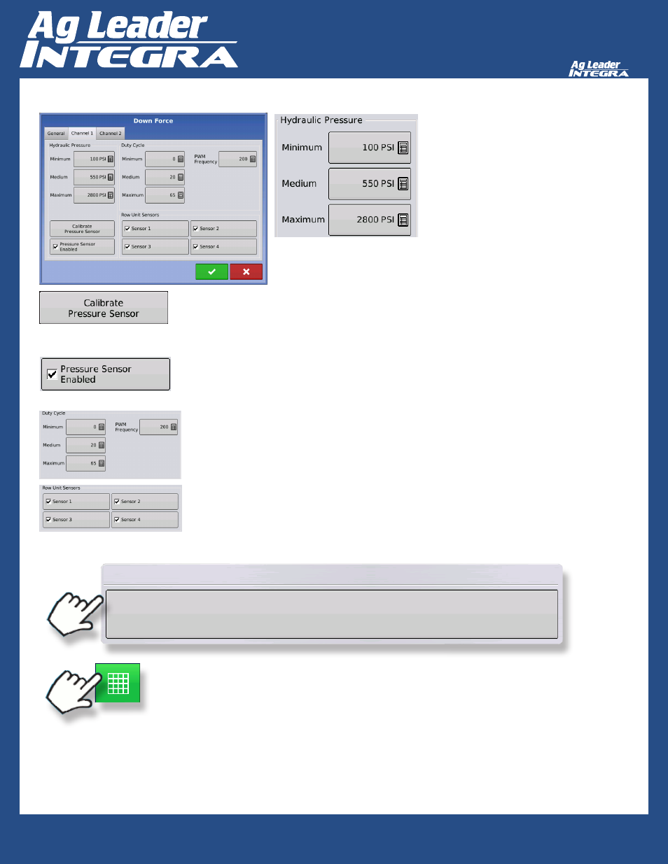
Hydraulic Downforce
Quick Reference Guide
AL: 2006350 ENG Rev B
Manually entered values depicting
tractor’s hydraulic pressure. Values shown
are for a 3000 PSI system (most common)
Duty Cycle
Minimum/Medium/Maximum: Manually entered values correlating PWM duty cycle to
hydraulic pressure supplied to Down Force actuators. Values shown are for the Ag
Leader supplied hydraulic down force valve.
PWM Frequency: Number of PWM signals per second (Hz)
To view run screen:
To start the Field Operation Wizard and load a configuration:
Configuration
Start Field Operation
Select Channel to Calibrate
1. Set Point: Enter value here that matches value displayed on the corresponding channel’s
mechanical gauge attached to Ag Leader Down Force valve. (This can be done at 0 PSI)
2. Slope: value is dependent on manufacture of pressure transducer. Use 0.75 PSI/mV for
transducer supplied with valve.
Pressure Sensor Enabled: must be enabled to display “Down Force” on run screen.
Row Unit Sensors
Enabled sensors will be used to calculate required supplemental down force