Chapter three, 1 controls and indicators, 2 understanding the leds – HP Integrity NonStop H-Series User Manual
Page 37
Section 2: HP 5242 Tape Drive
Chapter Three
3.1
Controls and Indicators
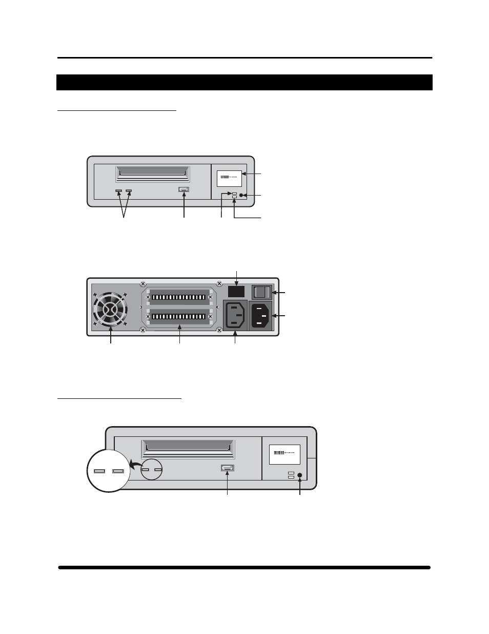
This chapter discusses the 5242 controls and indicators by function, location, and type. Figure 24 provides
views of the tape drive front panel and lists controls and indicators. Figure 25 shows the rear panel of the
tape drive and identifies all connectors and switches.
Programmable
Error-Alert LED
4-Line LCD,
8-Characters
per line
Write
E F
COMPRESS
2.3:1
Tape
Drive
LEDs
Eject
Button
Compression
Indicator LED
Mode
Switch
Figure 24
5242 front panel
O
l
Fan
AC Out
Power
Connector
AC In
Power
Connector
Power
Switch
SCSI
Connectors
AC Out
Power
Connector
Blank
Figure 25
5242 rear panel
3.2
Understanding the LEDs
The 5242 tape drive has two LEDs that communicate drive status. (See Figure 26. The LEDs can help
determine operating states.
Write
E F
COMPRESS
2.3:1
Detail
A
1
2
1
2
Tape
Clean/
Attn.
Eject
Button
Mode
Switch
Figure 26
5242 communication LEDs
HP StorageWorks DAT 72 (Models 5242 and 5242-ACL) User's Guide
30 HP Part Number 528296-03 July 2005