Mta relays, Metallic test access tb6 on hms-358 backplane – ADC HiGain H2TU-C-319 List 4E User Manual
Page 37
LTPH-UM-1049-02, Issue 2
Provisioning
H2TU-C-319 List 4E
January 9, 2002
29
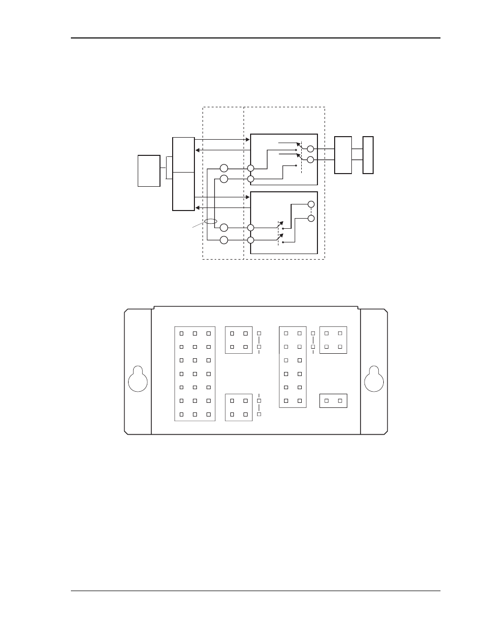
Metallic Test Access.
shows the block diagram of the metallic test access features which
are under control of the two relays, K1 and K2. The S2 metallic test access ports (IN or OUT) are bused to terminal
block TB6 located on the HMS-358 backplane, as shown in
below.
displays the location of
TB6 on the HMS-358 backplane.
Figure 10.
MTA Relays
Figure 11.
Metallic Test Access TB6 on HMS-358 Backplane
Both relays are energized or pulled down when the user either activates the MTA option from the front panel (or
the test menu) or upon command from the HMU. K1 opens the HDSL2 cable pair between the H2TU-Cs
transceiver and the incoming span and connects the latter to the Metallic Test Access Facilities (MTAF) OUT
T and R pins on TB6. K2 connects the HDSL2 transceiver to the Metallic Test Access Equipment (MTAE) IN
T and R pins on TB6. Typical MTAF and MTAE test interfaces are shown in
. A cable test
set connected to the out port of TB6 can be used to perform cable tests on the 2 wire HDSL2 cable pairs out to the
remote H2TU-R. Alternately, the OUT port of TB6 can connect to a golden H2TU-C which, in conjunction with
a T1 test set, can be used to perform system tests on the original circuit minus its H2TU-C and thus isolate any
trouble to the equipment or the facilities.
HMS-358
Backplane
HMS-358 Shelf
Defective H2TU-L
Standby H2TU-L
Test
center
MUX
AUX DSX-1
MUX DSX-1
TB6
Backplane
Jumpers
TB6
MTAE
MTAF
S3
S3
S3
S2
H
2
T
U
R
H
D
S
L
2
S
P
A
N
K2-S
K1-D
No connection
9
K
R
T
32
14
31
13
R
T
IN
OUT
S1
DACS
A-
TB6
SHIELD
SHIELD
B+
B-
SHIELD
METALLIC
TEST ACCESS
DSX-1
FAN
TB7
T
R
R
RING
T
TIP
2
1
SSC1
BITS TIMING
TEST ACCESS
TB4
TB3
SSC6
SSC5
SSC4
SSC3
SSC2
TB5
TB2
SYS ID
MIN VIS
MIN AUD
MAJ VIS
MAJ AUD
CRT VIS
NO
COM
NC
CRT AUD
COM
NO
A+
RX
TX
EXT A
C
O
OUT
IN