Connector pinouts, Appendix d – ADTRAN Express L768 User Manual
Page 135
61203192L1-20
Express L768 User Manual
D-1
Appendix D
Connector Pinouts
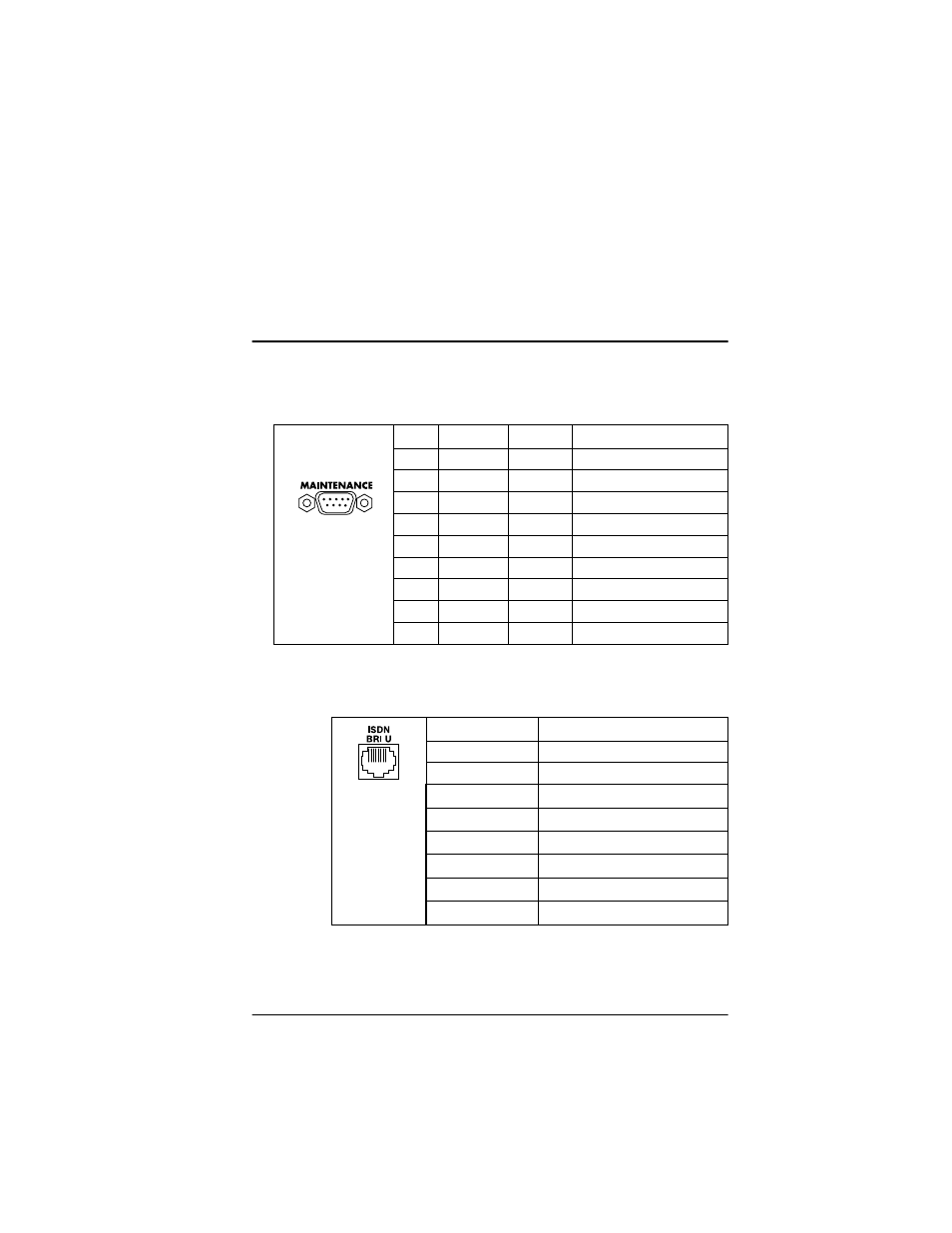
Table D-1. IBM/AT Style EIA-232 Interface
I = Input, O = Output, N/A = Not Applicable, N/C = Not Connected
Table D-2. RJ-45 HDSL BRI U
Pin
Name
I/O
Description
1
CD
N/C
Carrier Detect
2
RD
O
Receive Data
3
TD
I
Transmit Data
4
DTR
N/C
Data Terminal Ready
5
GND
N/A
Signal Ground
6
DSR
N/C
Data Set Ready
7
RTS
I
Request to Send
8
CTS
O
Clear to Send
9
RI
N/C
Ring Indicator
Pin
Description
1
Loop 1
2
Loop 1
3
no connection
4
Loop 2 (Express L1.5 only)
5
Loop 2 (Express L1.5 only)
6
no connection
7
no connection
8
no connection
See also other documents in the category ADTRAN Hardware:
- Express 4110 (205 pages)
- Gigabit Ethernet Multi-Mode Fiber Tributary Module 1184519L1 (2 pages)
- U-BR1TE ISDN 2B1Q (4 pages)
- DSU/CSU (6 pages)
- 3010 (30 pages)
- NetVanta 1024 (2 pages)
- FT1 (10 pages)
- IP Mini-DSLAM (2 pages)
- 6530 (2 pages)
- 6530 (20 pages)
- AHT1U (2 pages)
- DS3 MX (2 pages)
- 600R (264 pages)
- DUAL Nx56/64 1200142L1# (42 pages)
- NetVanta T1/FT1 + DSX-1 (2 pages)
- IQ SERIES 56 (1 page)
- 1200070L2 (187 pages)
- 1200051L2 (165 pages)
- NETVANTA 3120 (2 pages)
- 1200 (2 pages)
- NetVanta Series (2 pages)
- 850 (4 pages)
- ATLAS 800 Series Module QUAD E1 (2 pages)
- Atlas 830 (2 pages)
- TSU LT (2 pages)
- Express L1.5 (2 pages)
- MX2820-48 VDC M13 MUX (2 pages)
- Dial Backup Interface Module 1204006L2 (2 pages)
- 900 Series (2 pages)
- Atlas 550 (1 page)
- Atlas 550 (262 pages)
- NetVanta 5305 (2 pages)
- 1200350L1 (134 pages)
- ATM Mini-DSLAM (2 pages)
- D4-n x 64 DSU DP (4 pages)
- Type 400 (4 pages)
- 1204002L1 (163 pages)
- NetVanta ADSL (2 pages)
- 3000 HTU-C (2 pages)
- 600e (2 pages)
- 1200F (2 pages)
- D4 TRI-C DP (1 page)
- 239 T1 HDSL4 (20 pages)
- 3000 NTU-8 (18 pages)
- 1200130L1 (153 pages)