Set-up, Electrical connections, Table 4-1: tcm pin descriptions – PNI TCM User Manual
Page 13: 4set-up, 1 electrical connections
PNI Sensor Corporation
DOC#1014688 r06
TCM User Manual
– July 2013
Page 8
4
Set-Up
This section describes how to configure the TCM in your host system. To install the TCM into
your system, follow these steps:
Make electrical connections to the TCM.
Evaluate the TCM using TCM Studio or a binary terminal emulation program, such as
RealTerm or Tera Term, to ensure the compass generally works correctly.
Choose a mounting location.
Mechanically mount the TCM in the host system.
Perform a user calibration.
4.1
Electrical Connections
The TCM XB incorporates a 9 pin Molex connector, part number 53780-0970, which mates
with Molex part 51146-0900 or equivalent. The TCM MB incorporates a 4 pin Mil-Max
connector, part number 850-10-004-10-001000, which mates with Mill-Max part 851-XX-
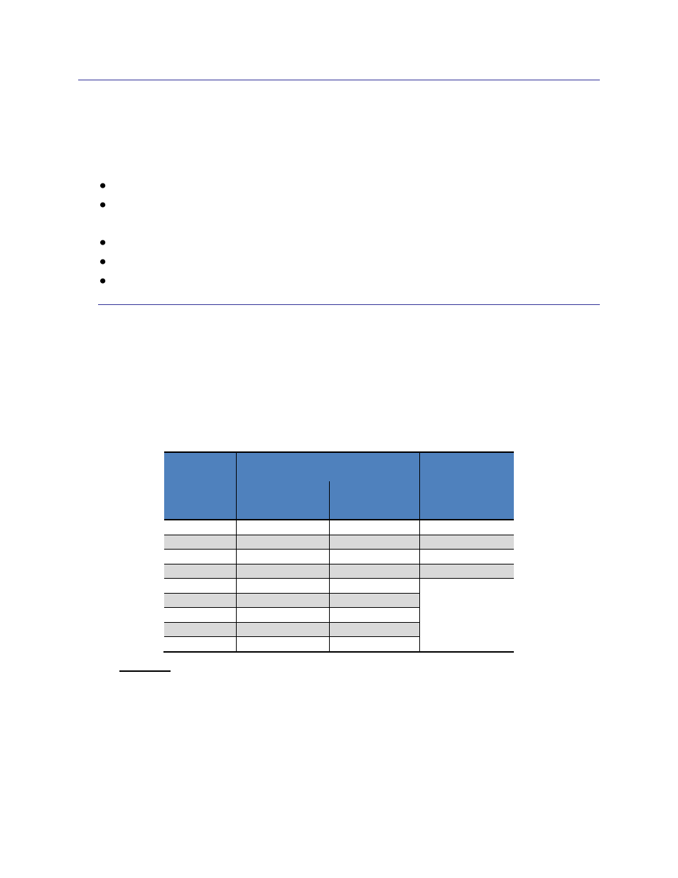
004-10-001000 or equivalent. The pin-out is given below in Table 4-1.
Table 4-1: TCM Pin Descriptions
Pin
Number
1
TCM XB
TCM MB
9 Pin
Connector
Cable Wire
Color
4 Pin
Connector
1
GND
Black
GND
2
GND
Gray
Vin
3
GND
Green
UART Tx
4
NC
Orange
UART Rx
5
NC
Violet
6
NC
Brown
7
UART Tx
Yellow
8
UART Rx
Blue
9
Vin
Red
Footnote:
1. For the TCM XB, pin #1 is indicated on Figure 3-1, while for the TCM MB, pin
#1 is the pin closest to the corner.
After making the electrical connections, it is a good idea to perform some simple tests to
ensure the TCM is working as expected. See Section 5 for how to operate the TCM with
TCM Studio, or Section 7 for how to operate the TCM using the PNI binary protocol.