Dwyer MTL5045 User Manual
Page 39
35
INM5000-6 Jul 2010
9
APPENDIX A - INSTRUCTIONS FOR
MTL5500 SERIES
9.1
MTL5521 rotational speed monitor
A rotational speed monitor with over- and under-speed monitoring, has
proximity detector input, conforming to NAMUR/DIN 19234
standard. Easy configuration is by two push buttons on the top of the
unit and the unit has a frequency range of 0.001Hz to 10kHz (0.06
to 600000 min-
1
). A liquid crystal display on the top of the unit
displays the current frequency. The 0/4 to 20mA current output is
proportional to the rotational speed, and the unit has SPDT relay
output for over- and under-speed indication. Start-up delay is initiated
by the closure of a normally open contact. Three power supply
versions are available – 24V DC, 115V AC and 230V AC.
9.1.1
Wiring connections
Hazardous-area terminals
5 & 6
NAMUR sensor input connection.
7 & 8
Normally open switch contact for Start-up delay
function.
Safe-area terminals
9 & 13
0/4 to 20mA analogue output.
10, 11 & 12
Over- and under-speed relay output.
15 & 16
Power supply connection.
9.1.2
LED indications.
Pulse indication:
Yellow - indicates an input pulse
Red - input circuit fault
Pwr Supply
voltage:
Green - device is operational
K
1
Limit value relay
Yellow - relay energized
9.1.3
Mounting instructions
The rotational speed monitor is suitable for either panel or DIN-rail
mounting. A minimum spacing of 3.5mm between the modules is
required when the modules are mounted horizontally. There is no
minimum spacing for vertically mounted units.
9.1.4
Configuration (figures 9.1 and 9.2)
Buttons S1 and S2 on the top of the unit are used to configure the
individual parameters of the unit. The required parameter Id, tb etc is
selected by pressing S2 until the parameter to be configured is displayed
and then, S1 must be pressed and held for approximately 3 seconds.
The left decimal will start flashing and the value can then be set, using
S1. S2 can then be used to adjust further decimals, the decimal point
and the exponent, in turn, returning eventually to the parameters menu.
Note:
The unit does not have internal error detection. Incorrect
parameters can lead to malfunction or failure of the device.
Note: All MTL products are tested for electrical safety to EN 61010 to
comply with the EC Low Voltage Directive.
See also warning on page 1.
9.1.4.1
Menu parameters
The following parameters can be configured:
id
User-specified identification number.
tb
Time basis. The standard time base setting is
frequency (Hz). If other units are required, a
conversion factor has to be used. A conversion from
Hz to revolutions per minute requires a tb value of 60,
the measured rotational speed is then multiplied by
the factor tb.
nt
Number of targets. The input frequency is divided by
the number of targets, nt.
F-0
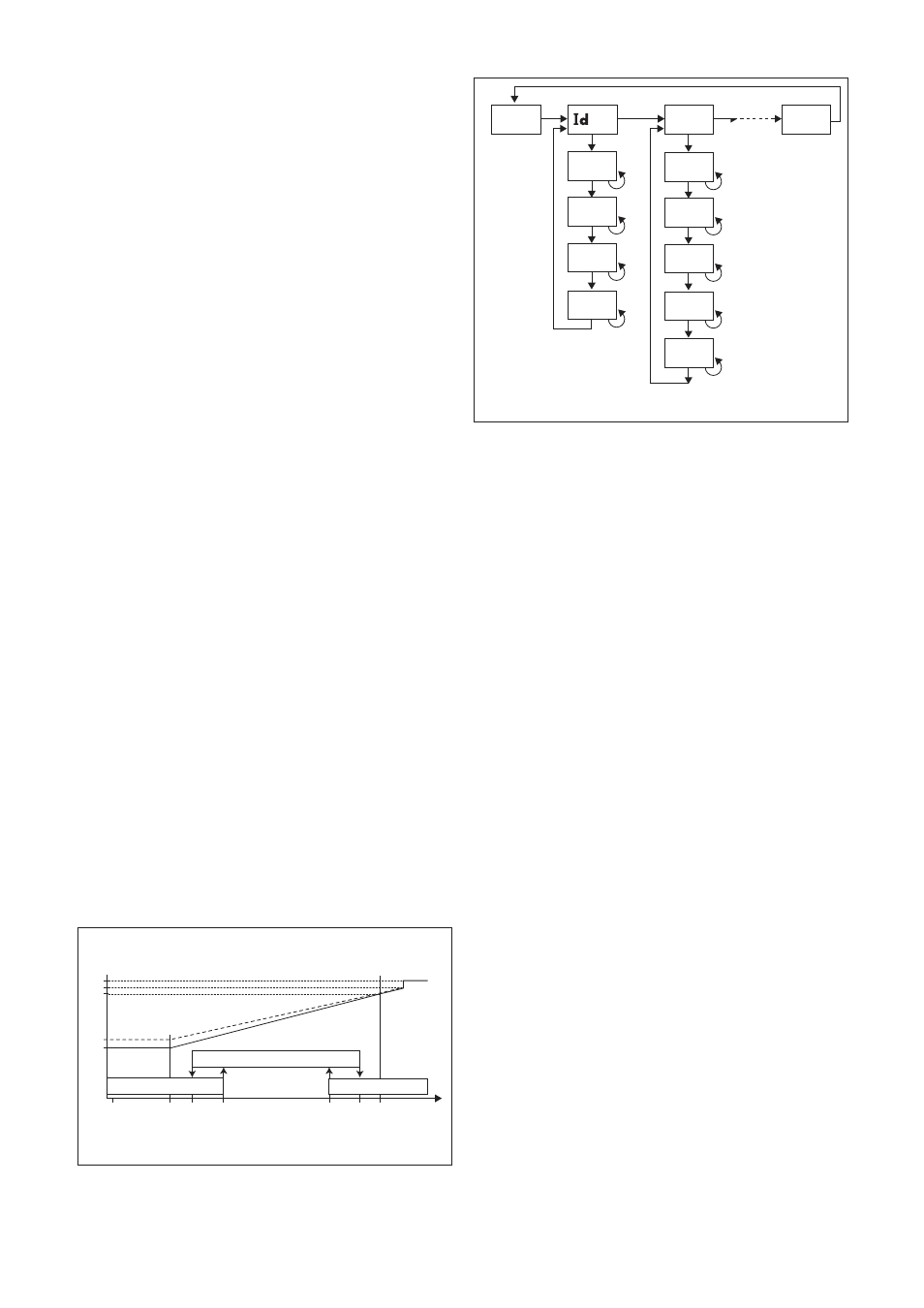
Zero speed detection. If the input frequency falls Uof Switch-off threshold for under-speed monitoring. If the Uon Switch-on threshold for under-speed monitoring. If the Oon Switch-on threshold for over-speed monitoring. If the Oof Switch-off threshold for over-speed monitoring. If the 9.1.4.2 Switching thresholds (figure 9.1) Once the parameters tb and nt have been set, all the threshold values 3 . If both the over- and under-speed monitoring modes are deactivated the Output current range: 0 to 20 mA or 4 to 20 mA. F-IL The minimum frequency to be indicated by either 0 or F-IH The maximum frequency for an output current of Tc Filter reaction time in seconds for smoothing the Start 8888 8888 8888 8888 8888 tb Soft S2 S1 (3 sec) S1 S1 S1 S1 S2 S2 S2 S2 S2 S2 S2 8888 8888 8888 8888 S1 S1 S1 S1 S1 S2 S2 S2 S2 S2 . . . S1 10 3 Figure 9.2: Configuration steps 24 22 20 4 0 Relay status OUT m A Relay de-energised F-0 F-IL UofUon Oon Oof F-IH f Relay energised Relay de-energised Figure 9.1: Configuration values
below the value F-0, the LCD display will show
'0000'. The value of F-0 must be less than the
switching threshold values, F-0
input frequency falls below the value Uof, the limit
value relay will de-energise.
input frequency rises above the value Uon, the limit
value relay will energise (Uof < Uon).
speed falls below the value Oon , the limit value
relay will energise.
speed rises above the value Oof, the limit value relay
will de-energise (Oon < Oof).
will be in the user-defined units. The difference between the switch-on
and switch-off threshold values allows user-defined switching hysteresis
to be set. The limit value relay and current output performance are
illustrated in figure 9.1.
To deactivate under-speed monitoring set Uof and Uon to 0.To deactivate
over-speed monitoring set Oof and Oon to 9999*10
relay operates as an alarm relay. If no errors occur during operation, the
relay is energized. If an error occurs in the input circuit, the relay de-
energizes.
Iout
4 mA, depending upon Iout.
20 mA. If F-IL > F-IH the output curve is reversed.