Dwyer MTL5045 User Manual
Page 16
12
INM5000-6 Jul 2010
6.1.2
Testing
Make the safe- and hazardous-area connections shown in figure 6.2
and check status LEDs and relay contacts as follows:
6.2
MTL5011B single-pole changeover
relay single-channel switch/
proximity detector with line fault
detection and phase reversal
The MTL5011B is similar to the MTL5011 but with added line fault
detection (LFD) facilities.
6.2.1
Wiring connections
See figure 6.3 for wiring connections.
Note: Reactive loads must be adequately suppressed.
6.2.2
Line fault detection
(See section 3.1.4 for definition of a line fault)
Input line faults (open- or short-circuit) are indicated by an LED and the
de-energising of the output relay. LFD is enabled/disabled by a switch
located on top of the module. Note that if the LFD facility is enabled for
switch inputs, the resistors shown in figures 6.3 and 6.4 MUST be fitted.
6.2.3
Testing
Make the safe- and hazardous-area connections shown in figure 6.4
and check the status of the output contacts as shown in table 6.1
Table 6.1
6.3
MTL5012 solid-state single-channel
switch/proximity detector with line
fault detection and phase reversal
The MTL5012 enables a safe-area load to be controlled, through a solid-
state output, by a switch or proximity detector in a hazardous area. Line
fault detection (LFD) and output phase reversal (see 3.1.3) facilities are
included.
Input
Phase
Status
Relay
switch
reverse switch
LED
contacts
Closed
Normal
On
Closed
Closed
Reverse
Off
Open
Open
Normal
Off
Open
Open
Reverse
On
Closed
Vs
Vs+
20 to 35V dc
+
3
2
1
6
5
4
7
8
9
10
11
12
13
14
Phase
Input
Output
Output
Channel
Line fault
reverse
Line fault
switch
relay
relay
LED
LED
switch
detection
(SW)
(11-12)
(10-11)
(yellow)
(red)
Normal
Off
a
Closed
Open
On
Off
Reverse
Off
a
Open
Closed
Off
Off
Reverse
Off
Open
Closed
Open
On
Off
Normal
On
Open
Open
Closed
Off
On
Normal
On
a
Open
Closed
On
On
Normal
On
b
Open
Closed
Off
Off
Normal
On
c
Closed
Open
On
Off
Terminal
Function
1
Input –ve
2
Input +ve
3
Earth leakage detection
10
Normally-closed contact
11
Common
12
Normally-open contact
13
Supply –ve
14
Supply +ve
6
5
4
3
2
1
7
8
9
10
11
12
13
14
Vs
Vs+
20 to 35V dc
Ch1
To earth
leakage
detector
SW
Ch1
22kW
680W
a
b
c
+
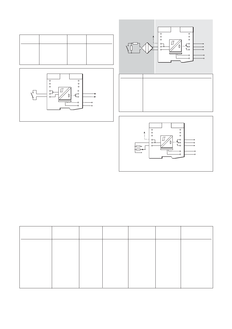
Figure 6.2: Test circuit for MTL5011
Figure 6.4: Test circuit for MTL5011B
6
5
4
3
2
1
7
8
9
10
11
12
13
14
Vs
Vs+
20 to 35V dc
Outpu
To earth
leakage
detector
22kW
680W
+
Resistors required only
for line fault detection
Figure 6.3: MTL5011B wiring diagram and connections
Hazardous area
Safe area