Mtl5053 – Dwyer MTL5045 User Manual
Page 30
26
INM5000-6 Jul 2010
6.25.2 Testing
Make the safe and hazardous-area connections shown in figure 6.56
and, substituting appropriate resistors at R
test
, carry out the following
checks.
6.26
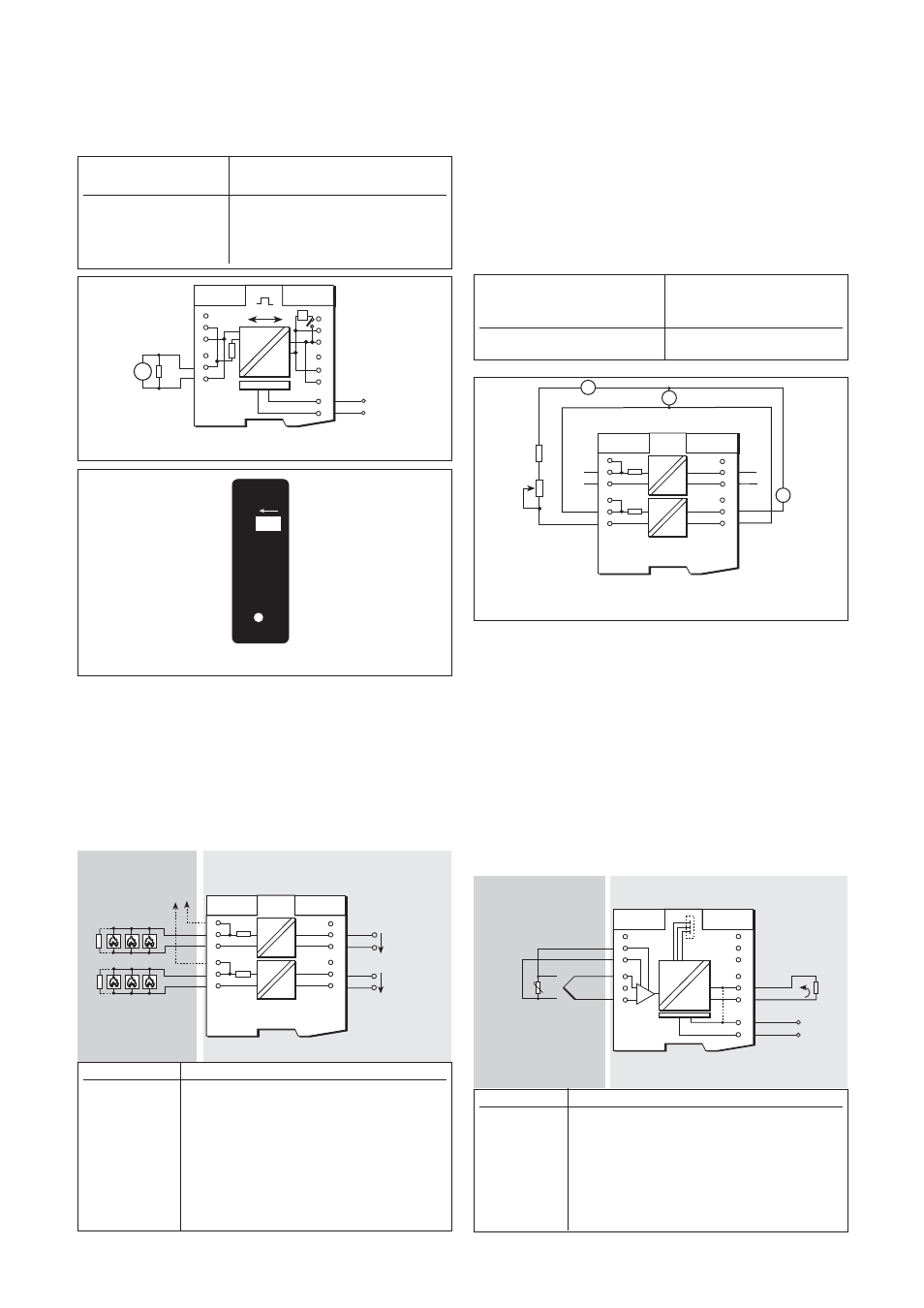
MTL5061 two-channel loop-powered
fire/smoke detector interface
The MTL5061 isolates two conventional fire and smoke detectors located
in hazardous areas. The triggering of a detector causes a
corresponding change in the safe-area circuit. The unit has reverse input
polarity, and 'non-fail' earth fault detection on either line can be
provided.
6.26.1
Wiring connections
See figure 6.59 for wiring connections.
6.26.2
'No-fail' earth fault protection
Protection is enabled by connecting earth leakage detectors, such as
MTL2220s (not CE marked), to the MTL5061; via terminal 3 or 6, or
both. To maintain isolation between the two channels, separate earth
leakage detectors are required. If a fault on either line of each channel
is detected, the unit continues working.
Note: The MTL2220 introduces a 100µA, 1Hz ripple to the field circuit.
6.26.3
Testing
Make the safe- and hazardous-area connections shown in figure 6.60
and, using RV1 to vary the output current, carry out the following check
for both channel 1 and channel 2:
6.27
MTL5074 temperature converters,
THC or RTD input
The MTL5074 converts low-level signals from temperature sensors
located in a hazardous area into 4 to 20mA signals for driving safe-area
loads.
Note: The earlier model MTL5073 had an internal link between
terminals 11 and 13. The MTL5073 model is discontinued.
6.27.1
Wiring connections
See figure 6.61 for wiring connections.
Note: for THC inputs requiring cold-junction compensation, a HAZ-CJC
hazardous-area connector (with integrated CJC sensor) is required not a
HAZ1-3 signal plug.
6
5
4
3
2
1
7
8
9
10
11
12
I
I
I
I
Ch 2 Fire detectors
+
To earth leakage
detector
Ch 1 Fire detectors
+
6 to
35V dc
6 to
35V dc
Ch 2
Ch 1
+
+
Figure 6.59: MTL5061 wiring diagram and connections
Hazardous area
Safe area
Output
Current
current
reading
(A2)
(A1)
10 to 40mA
<±400µA
6
5
4
3
2
1
7
8
9
10
11
12
I
I
I
I
Ch 2
+
+
Ch 2
24V
+
A1
A2
Ch 1
180W
2k
RV1
W
+
+
Figure 6.60: Test circuit for MTL5061
Hazardous area
Safe area
Figure 6.61: MTL5073/74 wiring diagram
7
8
9
10
11
12
13
14
6
5
4
3
2
1
mV
I
Vs
Vs+
20 to 35V dc
+
mV
Load
4-wire
3-wire
+
4/20mA
MTL5053
PWR
TERMINA
TOR
Figure 6.58: Top label, MTL5053
Voltage across
R
test
terminals 2 and 1 (V
1
)
Open-circuit
17.8 < V
1
<19V
220
Ω
11.5V 1 <13.5V 10 Ω V 1 <5V 6 7 10 13 T V V Vs+ Vs 20 to 35V dc R test V 1 + Figure 6.57 : Test circuit for MTL5053 Terminal Function 1 THC/EMF/RTD input –ve 3 THC/EMF/RTD input +ve 4 3-wire RTD input –ve 5 4-wire RTD input +ve 11 Output –ve 12 Output +ve 13 Supply –ve 14 Supply +ve Terminal Function 1 Output –ve (Ch 1) 2 Output +ve (Ch 1) 3 Earth leakage detection (Ch 1) 4 Output –ve (Ch 2) 5 Output +ve (Ch 2) 6 Earth leakage detection (Ch 2) 8 Input –ve (Ch 2) 9 Input +ve (Ch 2) 11 Input –ve (Ch 1) 12 Input +ve (Ch 1)
5
4
3
2
1
8
9
11
12
14