Dwyer GFT2 User Manual
Page 8
f) Totalizer #2 Auto Reload (Tabular entry)
This option allows to automatically reset/reload Totalizer #2 when it reaches preset
Action Volume value (when configured to count UP) or zero value (when configured
to count Down). This feature may be convenient for batch processing when
predefined volume of the fluid must be repeatedly dispensed into the process. The
following selections are available: Enabled or Disabled. The default entry is
Disabled. Totalizer #2 Auto Reload selections can be set with the UP and DN
buttons and are accepted by pressing the ENT button.
g) Totalizer #2 Auto Reset Delay (Numerical entry)
This option may be desirable when “Totalizer #2 Auto Reload” feature is enabled.
Valid settings are in the range of 0 to 3600 seconds (default value is 0, no delay).
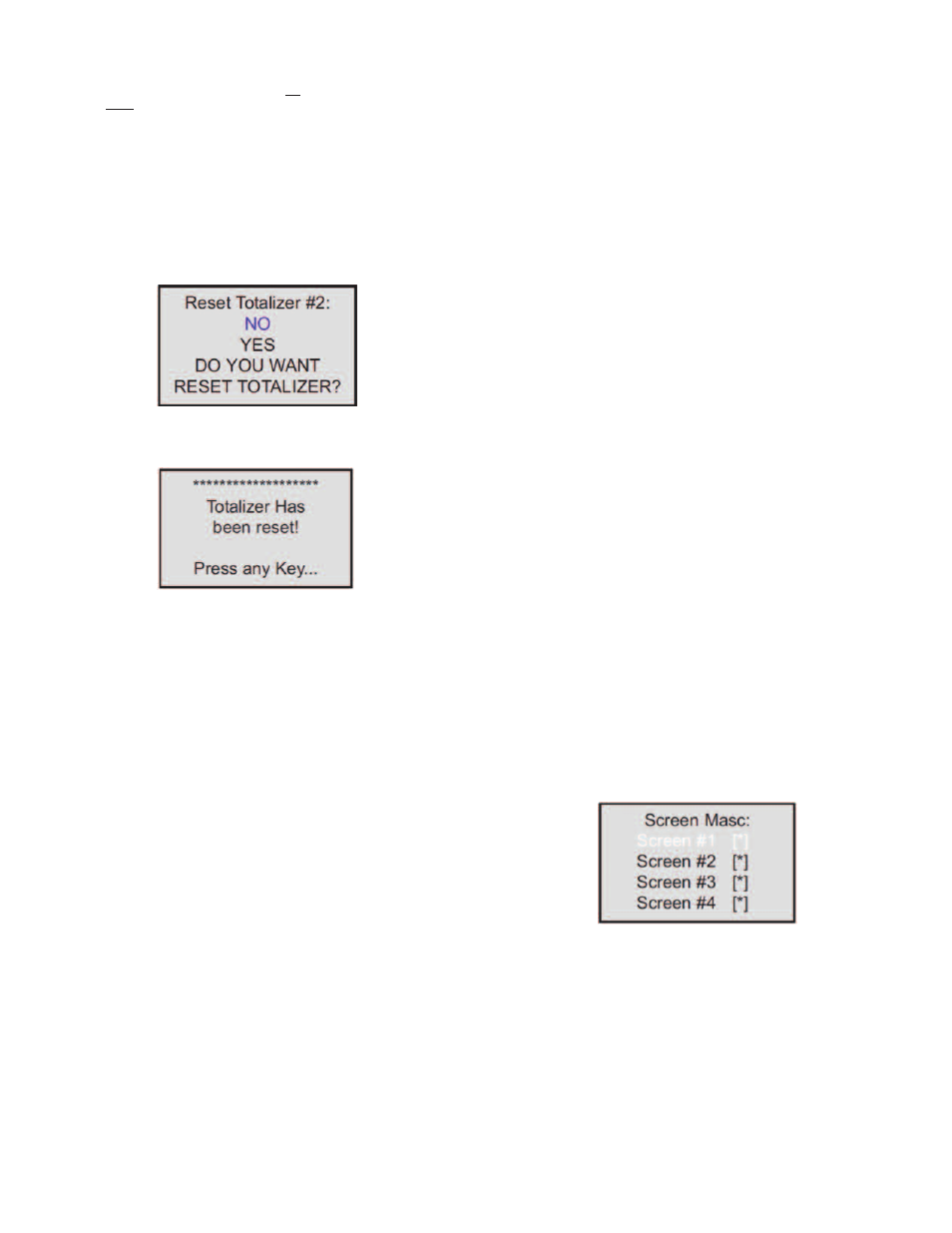
h) Reset Totalizer #2 (Numerical entry)
Totalizers #2 reading can be reset by selecting “Reset Totalizer #2” menu option. A
typical display with Totalizer #2 Reset screen is shown below.
Once “YES” option is selected, the Totalizer #2 will be reset and the following
confirmation screen will appear.
Submenu “Pulse Output”
The flow Pulse Output is operating independently from totalizers and, based on
configuration settings (see Figure 10), can provide pulse frequency proportional to
instantaneous fluid flow rate.
The LCD/keypad and serial communication interface commands are provided to:
• Enable/Disable Pulse Output
• Start Pulse Output at preset flow rate (0.0 – 100.0%FS.
• Configure the Unit/Pulse value (in current engineering units)
• Configure Pulse Active On Time (10 – 6553 milliseconds)
NOTE: The Pulse Output minimum Active On time is 10 milliseconds (.01 second).
The Optical Pulse Output cannot operate faster than one pulse every 100
millisecond (.1 second). A good rule to follow is to set the Unit/Pulse value equal to
the maximum flow in the same units per second. This will limit the pulse rate to no
faster than one pulse every second.
For example:
Maximum flow rate = 1200 kg/min
(1200 kg/min = 20 kg/sec)
If unit per pulse is set to 1200 kg/pulse, the Optical Pulse
Output will pulse once every minute.
If unit per pulse is set to 20 kg per pulse, the Optical Pulse Output will pulse once
every second.
The Optically-Isolated Pulse Output incorporate Pulse Output queue, which
accumulate pulses if the Pulse Output is accumulating process flow faster than the
Pulse Output hardware can function. The queue will allow the pulses to “catch up”
later if the flow rate decreases. A better practice is to slow down the Pulse Output
by increasing the value in the Unit/Pulse setting in the Pulse Output menu (see
Figure 10).
NOTE: If Pulse Output feature is required, one of the Digital Optically- solated
outputs must be assigned to “Pulse Output” function. Pulse output signal will be
accessible via corresponding Digital Optically-Isolated output on the screw
terminal header J1 (see Wiring Diagrams).
Submenu “Opt. Outputs Settings”
Two sets of optically-isolated digital outputs are provided to actuate user-supplied
equipment. These are programmable via digital interface or LCD/Keypad such that
the outputs can be made to switch when a specified event occurs (e.g. when a Low
or High Flow Alarm limit is exceeded or when the Totalizer reaches a specified
value) or it may be directly controlled by user.
The user can configure each optical output action from 9 different options:
• Disabled: No Action (output is not assigned to any events and is not energized)
• Low Flow Alarm
• High Flow Alarm
• Range between High and Low Flow Alarm settings
• Totalizer #1 reading exceed set limit
• Totalizer #2 reading exceed set limit
• Pulse Output function
• Diagnostic: Output will be energized when any of the Diagnostic or System events
are active
• Manual On Control: Output will be energized until Disabled option will be selected.
By default, both optically-isolated outputs are disabled.
NOTE: Optically-isolated outputs are accessible via screw terminal header J1 and
require application of external DC voltage across terminals. See Wiring Diagrams.
Submenu “Display Settings”
Process Information screens can be configured to be static (manual control) or
dynamic (automatic sequencing). In the static mode pressing the UP button allows
the user to page through the PI screens in the forward direction, pressing DN button
pages through the PI screens in the reverse direction. When the last PI screen is
reached, the firmware “wraps around” and scrolls to the initial PI screen once again.
NOTE: PI screens which are masked in the Screen Mask Register (see below) will
be skipped.
Use the “General Settings” menu to navigate to “Display Settings” menu option
(see Figure 10).
The following settings are available for LCD Display:
a) Display Mode (Tabular entry)
This option determines whether Display screens are in static (manual control) or
dynamic (automatic sequencing) mode. The following selections are available:
Static or Dynamic. The default entry is: Static (manual control). Display screens
mode parameter can be set with the UP and DN buttons and are accepted by
pressing ENT button.
b) Screen Cycle Time (Numerical entry)
This menu selection defines time interval in seconds for each PI screen to be
displayed in the dynamic mode (automatic sequencing). Screen Cycle Time can be
set to any value in the range between 1 to 3600 seconds (1 hour, numerical entry).
c) Screen Mask (Tabular entry)
Using Screen Mask settings the user can enable (unmask) or disable (mask) up to
4 different process variable combinations (see Figure 1). By default the unit is
shipped from the factory with all PI screens enabled. A typical display with Screen
Mask selection is shown below.
In the example shown above, all PI screens are enabled. Each PI screen assigned
to a corresponding bit in the PI Screen Register. In order to change PI Screen mask
settings, the user should select the desired screen using UP and DN buttons and
then press RIGHT button. The asterisk will appear/disappear on the right side of the
corresponding screen. The asterisk represents that the screen is enabled. In order
to disable the screen, the corresponding asterisk must be removed. Use the ENT
button to accept and save new PI Screen Mask settings in the device’s nonvolatile
memory.
NOTE: PI Screen #1 cannot be disabled (unmasked).
d) Display Back Light (Numerical entry)
Using Display Back Light settings the user can adjust the desired level of the LCD
back light. The backlight has 19 different levels. Use UP and DN buttons to adjust
back light level and press ENT button to accept and save back light level settings
in the device’s nonvolatile memory.
Figure 16
Figure 17
Figure 18