Dwyer GFT2 User Manual
Page 13
An optional cables kit assembly is available for order:
c) Input/Output Jumper Configuration
NOTE: The GFT2 device input/output jumpers were configured at the factory
according to the order. There is no need to change input/output jumpers
configuration unless a different input is being used. Before applying power and
process signals, make sure the input/output jumpers are installed in the correct
positions. See Table 6.
d) Parameters Configuration
The following parameters must be configured:
• Device Function (see Submenu “Device Function”). “Meter function has to be
selected.
• Full-Scale Range (see Submenu “Device Calibration”). Full-Scale Range
parameter has to be set equal to the GFM full-scale flow rate in L/min.
• Fluid Std. Density (see Submenu “Device Calibration”). This parameter is required
only when mass-based engineering units are selected.
NOTE: If “Full-Scale Range”, “Device Function”, and “Fluid Std. Density”
parameters are not set properly, the device may have erroneous readings and
unpredictable behavior.
User may configure other parameters according to individual preferences and
application requirements.
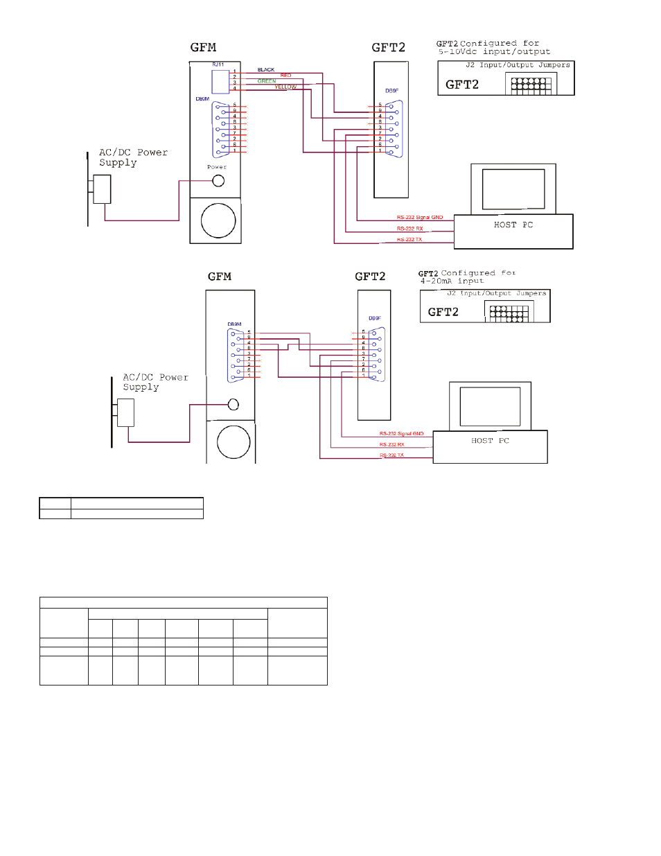
Figure 33: Connecting GFT2 to the GFM using 5-10 VDC output from RJ11 connector.
Figure 34: Connecting GFT2 to the GFM using 4-20mA output from DB9 connector.
Model
A-646
Description
Flow Meter Mounting Kit, No Cables
Input/Output Jumper Configuration Options for GFM Series Flow Meters
PV Input
Type
(GFT2 Input)
0 to 5 VDC
0 to 10 VDC
4 to 20 mA
J2 Jumper Configuration
J2A
2 to 3
2 to 3
2 to 3
J2B
5 to 6
5 to 6
5 to 6
J2C
8 to 9
8 to 9
8 to 9
Note
249 Ω passive,
not isolated
current output
J2D
10 to 11
11 to 12
10 to 11
J2D
14 to 15
14 to 15
13 to 14
J2F
17 to 18
17 to 18
16 to 18
Table 6