Dwyer GFT2 User Manual
Page 11
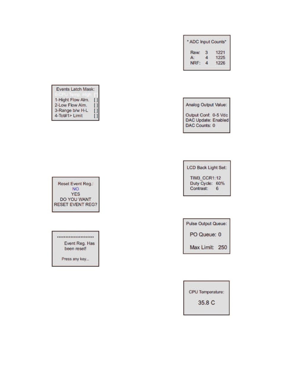
In Figure 23, latch features for all events are disabled except event #0. In order to
change Event Latch Mask Settings the user should select desired event using UP
and DN buttons and then press RIGHT button. The asterisk will appear/disappear
on the right side of the corresponding event. The asterisk represents that the latch
feature is enabled. In order to disable latch feature, the corresponding asterisk has
to be removed. Use the ENT button to accept and save new Event Latch mask
settings in the device’s non volatile memory.
c) Event Register Mask (Tabular entry)
Using Event Register Mask Settings user can individually enable (unmask) or
disable (mask) each event. The event is enabled if an asterisk sign [*] is set on the
right across from corresponding event. If the event is disabled, it will not be
processed or indicated in the Events Status Register, even if actual conditions for
event have occurred. By default the unit is shipped from the factory with only one
event active: “0 – CPU Temperature too high”. All other events are disabled. A
typical display with Event Register Mask selection is shown below.
In the example shown above, all events are disabled except event #0. In order to
change Event Register Mask Settings, the user should select the desired event
using UP and DN buttons and then press the RIGHT button. The asterisk will
appear/disappear on the right side of the corresponding event. The asterisk
represents that the event is enabled. In order to disable the event, the
corresponding asterisk has to be removed. Use the ENT button to accept and save
the new Event Register Mask Settings in the device’s nonvolatile memory.
d) Reset Event Register (Tabular entry)
The Event Register can be reset by selecting “Reset Event Register” menu option.
A typical display with the Reset Event Register screen is shown below.
Once the “YES” option is selected, the Event Register will be reset and the
following confirmation screen will appear.
Submenu “Diagnostic Menu”
The Diagnostics Menu can be used for troubleshooting purposes and provides
information about the device’s internal variables. These items (except the Events
Register submenu described above) are informational only and may not be
changed (read only).
a) ADC Input Counts (Read Only)
This menu selection provides raw, average, and filtered values of the ADC counts
for analog input circuitry (read only). A typical display with the ADC Input Counts
screen is shown below.
b) Analog Output Values (Read Only)
This menu selection provides information about currently selected analog output
configuration and DAC counts for analog output circuitry (read only). A typical
display with DAC Output Values screen is shown below.
c) LCD Back Light Settings (Read Only)
This menu selection provides information about the LCD back light level, PWM duty
cycle, and contrast (read only). A typical display with the LCD Back Light Settings
screen is shown below.
d) Pulse Output Queue (Read Only)
This menu selection provides information about the Pulse Output Queue. A typical
display with the Pulse Output Queue screen is shown below.
e) CPU Temperature (Read Only)
This menu selection provides the current value of the PCB and CPU temperature
in °C (read only). A typical display with the CPU Temperature reading is shown
below.
Figure 24
Figure 25
Figure 26
Figure 27
Figure 28
Figure 29
Figure 30
Figure 31