Dwyer GFT2 User Manual
Page 16
c) Input/Output Jumper Configuration
NOTE: The GFT2 device input/output jumpers were configured at the factory
according to the order. There is no need to change input/output
jumpers’configuration unless a different input is being used. Before applying
power and process signals, make sure the input/output jumpers are installed in
the correct position. See Table 9.
d) Parameters Configuration
The following parameters have to be configured
• Device Function (see Submenu “Device Function”). If GFT2 is connected to
flow controller, then “Controller” function has to be selected. If GFT2 is
connected to the flow meter, then “Meter” function has to be selected
• Full-Scale Range (see Submenu “Device Calibration”). Full-Scale Range
parameter must be set equal to the mated device full-scale flow rate in L/min.
• Fluid Std. Density (see Submenu “Device Calibration”). This parameter is
required only when mass-based engineering units are selected.
NOTE: If “Full-Scale Range”, “Device Function”, and “Fluid Std. Density”
parameters are not set properly, device may have erroneous reading and
unpredictable behavior
User may configure other parameters according to individual preferences and
application requirements.
Troubleshooting
Common Conditions
The GFT2 Totalizer Input/Output Flow Monitor/Controller was thoroughly
checked at numerous quality control points during and after manufacturing and
assembly operations. It was calibrated according to the input and output
configuration. It was carefully packaged to prevent damage during shipment. If
instrument is not functioning properly, please check for the following common
conditions:
• Are all cables connected correctly?
• Were the connector pin outs matched properly?
• Are J2 input/output jumpers configured correctly?
• Is the power supply correctly selected according to requirements?
When several devices are used, a power supply with appropriate current rating
should be selected. When interchanging with other manufacturers’ equipment,
cables and connectors must be carefully wired for correct pin configuration.
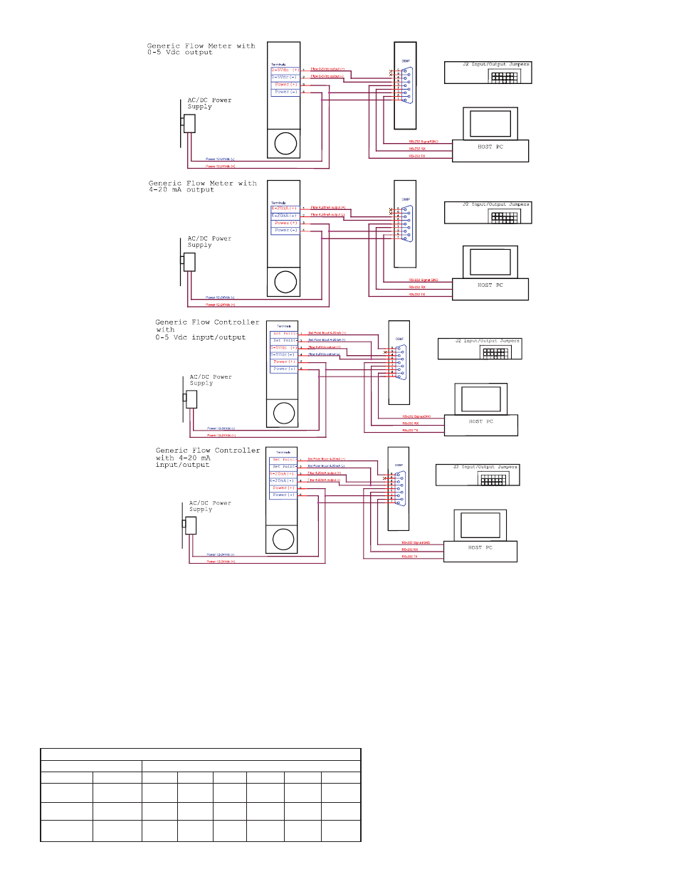
GFT2
GFT2
GFT2
GFT2
Figure 38: Connecting GFT2 to the Generic Flow Meter
GFT2
GFT2
GFT2
GFT2
Figure 39: Connecting GFT2 to the Generic Flow Controller
Input/Output Jumper Configuration Options for Generic Flow Meters and Controllers
Output
0 to 5 VDC
4 to 20 mA
0 to 10 VDC
J2 Jumper Configuration
J2A
2 to 3
1 to 2
2 to 3
J2B
5 to 6
4 to 5
5 to 6
J2C
8 to 9
7 to 8
8 to 9
J2D
10 to 11
10 to 11
11 to 12
J2D
14 to 15
13 to 14
14 to 15
J2F
17 to 18
16 to 17
17 to 18
GFT2
Input
0 to 5 VDC
4 to 20 mA
0 to 10 VDC