Dwyer GFT2 User Manual
Page 2
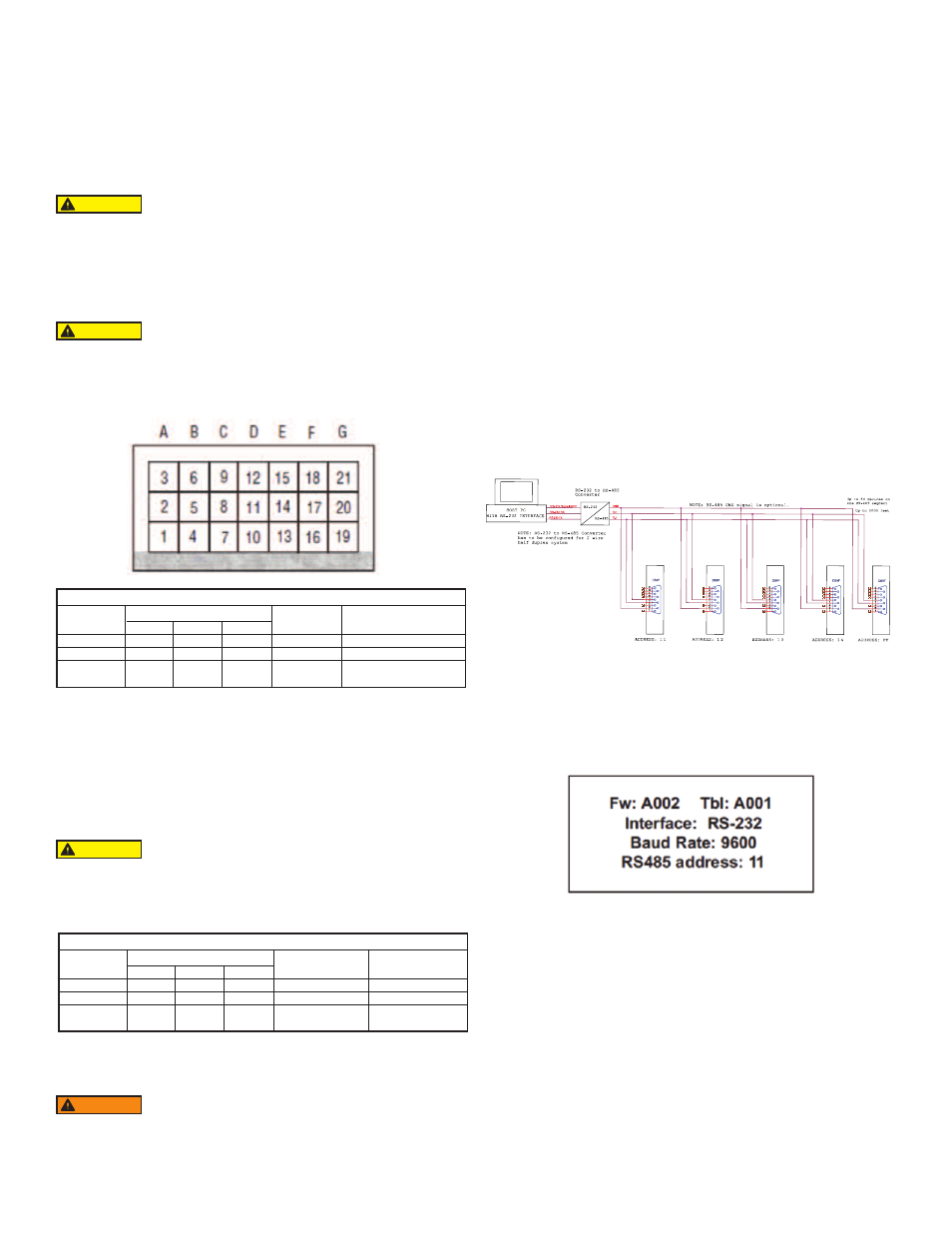
The power supply (PS), process variable (PV) input, set point (SP) control output, and
serial communication interface signals are connected to the GFT2 via miniature 9 pin
female “D” connector.
Power Supply Connections
The power supply requirements for the GFT2 are: 12 to 26 VDC, (unipolar power
supply).
DC Power (+) --------------- Pin 4 of the 9 pin “D” connector
DC Power (-) --------------- Pin 8 of the 9 pin “D” connector
Power Variable (PV) Input Signal Connections
Depending on jumper J2 configuration, input signal can be set to 0 to 5, 0 to 10VDC,
or 4 to 20 mA.
Set Point (SP) Output Signal Connections
Set Point (SP) output signal connection is only required if the GFT2 is mated to the
flow controller and will be used as a source for Set Point control signal. Depending on
the jumper J2 configuration, the SP output signal can be set to 0 to 5, 0 to 10 VDC or
4 to 20 mA.
RS-232 Serial Communication Interface Connections
The digital interface operates via RS-232 and provides access to all applicable
internal configuration parameters and data.
The settings for the RS-232 communication interface are:
Baud rate:
default 9600 baud
Stop bit:
1
Data bits:
8
Parity: None
Flow control: None
The RS-232 Communication Interface Connection must establish a crossover
connection form the PC host connector to the “D” connector.
RS-232 RX: Pin 2 on the host PC DB9 connector - Pin 7 of the 9 pin “D” connector
(TX-)
RS-232 TX: Pin 3 on the host PC DB9 connector - Pin 3 of the 9 pin “D” connector
(RX-)
RS-232 Signal GND: Pin 5 on the host PC DB9 connector - Pin 6 of the 9 pin “D”
connector
RS-485 Communication Interface Connection:
The RS-485 converter/adaptor must be configured for: multidrop, 2-wire, half duplex
mode (see Figure 6). The transmitter circuit must be enabled by TD or RTS
(depending on which is available on the converter/adapter). Settings for the receiver
circuit should follow the selection made for the transmitter circuit in order to eliminate
echo.
RS-485 T(-) or R(+)
pin 7 of the 9 pin “D” connector (TX-)
RS-485 T(+) or R(-)
pin 3 of the 9 pin “D” connector (RX+)
RS-485 GND (if available)
pin 6 of the 9 pin “D” connector
LCD Key-Pad Operation: Data Entry and Configuration
Display Indications:
Initially, after the power is first turned on, the banner screen is shown for 2 seconds,
then the device firmware and EEPROM data base table revisions on the first line,
communication interface type on the second line, baud rate and RS-485 hexadecimal
address value on the third and fourth lines are shown for another 2 seconds.
Subsequently, the actual process information (PI) is displayed.
Based on configuration (device function as flow meter or flow controller), different
parameters may be displayed in the Process Information (PI) screen by pressing the
UP or DN pushbuttons.
Process Information screens can be configured to be static or dynamic. Using the
Screen mask settings, the user can enable (unmask) or disable (mask) up to 4
different process information combinations (see Figure 6). In static mode the UP
button pages through the PI screens in the forward direction, the DN button pages
through the PI screens in the reverse direction. When the last PI screen is reached,
the firmware “wraps around” and scrolls to the initial PI once again.
In the Dynamic display mode, firmware initiates automatic screen sequencing with
user-adjustable screen Cycle Time. When the last PI screen is reached, the firmware
“wraps around” and scrolls to the initial PI screen once again.
NOTE: Actual content of the LCD screen may vary depending on the model and
device configuration.
-Do not apply power voltage above 28 VDC. Doing so will
cause device damage or faulty operation.
-Make sure power is OFF when connecting or disconnecting any cables or wires in
the system.
CAUTION
When connecting the external signals to the input terminals,
always check actual jumper J2 configuration. Do not exceed the
rated values shown in the specifications in Table 2. Failure to do so might cause
damage to this device. Be sure to check if the wiring and the polarity of the power
supply and PV signals are correct before turning the power ON. Wiring error may
cause damage or faulty operation.
CAUTION
The 4 to 20 mA current loop output is self-powered (non-
isolated). Do NOT connect an external voltage source to the
output signals.
WARNING
When connecting the load to the output terminals always check
actual jumper J2 configuration. Do not exceed the rated values
shown in Table 3. Failure to do so might cause damage to this device. Be sure to
check if the wiring and the polarity of the power supply and SP signals are correct
before turning the power ON. Wiring error may cause damage or faulty operation.
Do not connect external voltage source to the SP output terminals.
CAUTION
GFT2#1
GFT2#2
GFT2#3
GFT2#4
GFT2#N
Figure 1 RS-485 Multidrop Half Duplex Two Wire System
Figure 2
Maximum Rated Values for PV Input Signals
PV Input
Type
0 to 5 VDC
0 to 10 VDC
4 to 20 mA
J2 Jumper Configuration
J2D
10 to 11
11 to 12
10 to 11
J2E
14 to 15
14 to 15
13 to 14
J2F
17 to 18
17 to 18
16 to 17
Maximum
Signal Level
≤6 VDC
≤11 VDC
≤25 mA
Note
249 Ω Passive, Not
Isolated Current Input
Table 2
DC Power (+) --------------- Pin 4 of the 9 pin “D” connector
DC Power (-) --------------- Pin 8 of the 9 pin “D” connector
Maximum Rated Load Impedence for SP Output Signals
SP Output
Type
0 to 5 VDC
0 to 10 VDC
4 to 20 mA
J2 Jumper Configuration
J2A
2 to 3
2 to 3
1 to 2
J2B
5 to 6
5 to 6
4 to 5
J2C
8 to 9
8 to 9
7 to 8
Maximum
Load Impedence
≤1000 Ω
≤5000 Ω
≤900 Ω
Note
Self powered
(non-isolated)
Table 3
DC Power (+) --------------- Pin 5 of the 9 pin “D” connector
DC Power (-) --------------- Pin 8 of the 9 pin “D” connector