Dwyer GFT2 User Manual
Page 15
Based on interface being used and power supply option, optional cable kit
assemblies are available for order. See Table 7 for optional GFC cable kit
assemblies.
c) Input/Output Jumper Configuration
NOTE: The GFT2 device input/output jumpers were configured at the factory
according to the order. There is no need to change the input/output jumper
configuration unless a different input is being used. Before applying power and
process signals, make sure the input/output jumpers are installed in the correct
position. See Table 8.
d) Parameters Configuration
The following parameters have to be configured:
• Device Function (see Submenu “Device Function”). “Controller” function has to
be selected.
• Full-Scale Range (see Submenu “Device Calibration”). Full-Scale Range
parameter must be set equal to the GFC full-scale flow rate in L/min.
• Fluid Std. Density (see Submenu “Device Calibration”). This parameter is
required only when mass-based engineering units are selected.
NOTE: If “Full-Scale Range”, “Device Function”, and “Fluid Std. Density”
parameters are not set properly, device may have erroneous reading and
unpredictable behavior.
User may configure other parameters according to individual preferences and
application requirements.
Connecting GFT2 to Flow Meters/Controllers From Other Manufacturers
(Stand Alone)
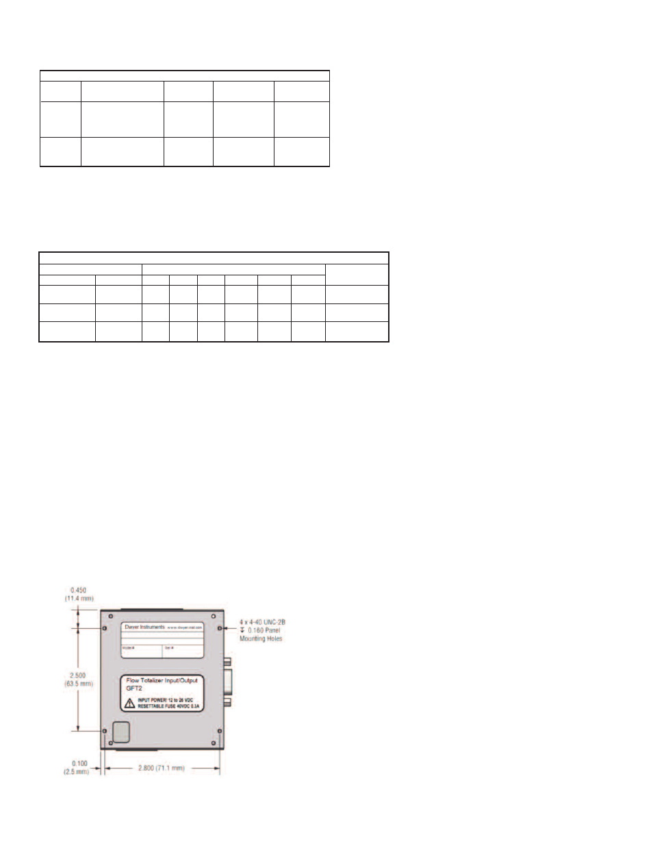
a) Mounting
When GFT2 is connected to flow meters/controllers from other manufacturers, it
can be used as stand alone table top or panel mounted (See Figure 37). On the
back side of the GFT2 enclosure, there are 4 tapped holes which are designated to
be used for panel-mounted option.
b) Electrical Connection
GFT2 can be used with any generic flow meter/controller which can support 0 to 5
VDC and/or 4 to 20 mA input/output interfaces. It can also be ordered for 0 to 10
VDC input/output interface (special order, not supported by generic models).
NOTE: Do not connect GFT2 input/output circuitry to voltages above 5.5 VDC
unless GFT2 was specifically ordered for 0-10 VDC input/output interface. Check
device part number or contact Dwyer Instruments customer service for device
input.
Optional GFC Power Supply/Cables and Mounting Kit Assemblies
Kit Part
Number
GFT2-20C
A-645
Description
Shielded cable with
plug 110 VAC to
12 VDC power supply,
communication branch
GFC flow controller
mounting kit, no cables,
no power supply
GFT2
Input/Output
0 to 5 VDC
N/A
Communication
Interface Cable
Yes
N/A
GFC Power
Supply Option
12 VDC Only
N/A
Table 7
Input/Output Jumper Configuration Options for GFC Series Flow Controllers
Output
0 to 5 VDC
4 to 20 mA
0 to 10 VDC
J2 Jumper Configuration
J2A
2 to 3
1 to 2
2 to 3
J2B
5 to 6
4 to 5
5 to 6
J2C
8 to 9
7 to 8
8 to 9
GFC Cable Kit
GFT2-20C or
A-645
Not supported by
GFC cable kits
Not supported
by GFC
J2D
10 to 11
10 to 11
11 to 12
J2D
14 to 15
13 to 14
14 to 15
J2F
17 to 18
16 to 17
17 to 18
GFT2 PV Type
Input
0 to 5 VDC
4 to 20 mA
0 to 10 VDC
Table 8
Figure 37