Dwyer GFT2 User Manual
Page 3
When GFT2 device is set as the last device on the RS-485 bus segment, and 220
Ohm bus termination is required, set jumper J2G to position 19-20. This will result
in connection 220 Ohm resistor between RS-485 (+) and (-) terminals.
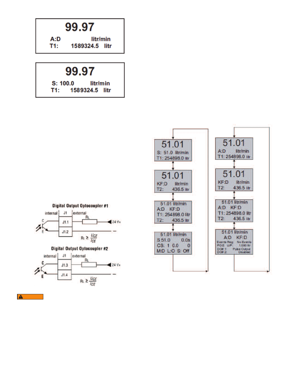
Digital and Pulse Optically-Isolated Outputs and Connections
GFT2 is equipped with two programmable digital optically-isolated outputs. Each
output can be assigned to any one of many different system events or configured
as pulse output.
Digital optically-isolated outputs use dedicated 4 position 3.5 mm male terminal
block header J1 located on the top side of the GFT2 enclosure . (Mated interface
connector: Tyco Electronics P/N 284510-4)
Optocoupler #1 - Terminal J1 (pins 1 and 2):
Plus (+) (passive)
Terminal J1 pin 1
Minus (-) (passive)
Terminal J1 pin 2
Optocoupler #2 – Terminal J1 (pins 3 and 4):
Plus (+) (passive)
Terminal J1 pin 3
Minus (-) (passive)
Terminal J1 pin 4
Set Point Control (only for devices set as controller)
When the GFT2 is configured as controller it can be used to control the set point
value for mated flow controller using the analog output interface. The set point
value can be adjusted locally using the LCD/ keypad, remotely via RS-232/RS-485
digital interface, or can be programmed in advance using user preset programs of
up to sixteen steps (Program Set Point Mode).
NOTE: Before applying power and process signals, make sure the input/output
jumpers are installed in the correct position (see Figure 6).
Adjusting the Set Point using local LCD/Keypad: Current Set Point value is
displayed on the second line of the main PI screen, next to the ‘S’ character. See
Figure 7.
Pressing the ENT button while in the PI screen will activate Set Point adjustment
mode. The first character of the Set Point value will start to flash. Use the UP or DN
button to increase/decrease digit value from 0 to 9. Use RIGHT or LEFT buttons to
move the cursor to another digit position. When desired Set Point value is entered,
use the ENT button to accept the new Set Point value. If in the end of the Set Point
value entry the ESC button is pressed instead of ENT, the original Set Point value
will be restored and Set Point adjustment mode will be deactivated. To exit form the
Set Point adjustment mode before Set Point value is accepted, press ESC button.
NOTE: Since the Set Point value entered via local LCD/keypad is stored in the non
volatile memory (EEPROM), it will be executed on the next device power up event.
NOTE: If Program Set Point mode is enabled and the program is running, the Set
Point value can be changed at any moment by the execution of the next active step.
Controlling Set Point value using Program Set Point Mode:
In order to activate the Programmed Set Point:
1. Program Set Point mode has to be enabled.
2. Program Loop parameter has to be set to desired value (On/Off).
3. Program Run parameter has to be set to “On”.
Figure 5
Figure 3 - Initial PI Screen (Flow Meter)
Figure 4 - Initial PI Screen (Flow Controller)
Optically-isolated outputs require application of external DC
voltage across terminals. Do not exceed maximum allowed
limits for voltage and current: 2V < UCE < 40 V, 0.2 mA < ICE < 150 mA.
WARNING
Figure 6