Dwyer GFT2 User Manual
Page 12
Installation
General Directions
• Mounting, electrical installations, parameters configuration, startup, and
maintenance of this instrument may only be performed by trained personnel.
Personnel must read and understand this operating manual before performing any
installation or configuration steps.
• The GFT2 device should only be operated by trained personnel. All instructions in
this manual are to be observed.
• Ensure that power and all input/output signals are correctly wired up according to
the wiring diagram provided in this manual. The housing of the device should only
be opened by trained personnel.
Hardware Installation
NOTE: Electrostatic discharge may cause permanent damage to the electronic
circuitry. Before installing or connecting any wires, the installer must discharge
himself by touching the building’s protective Earth ground.
The GFT2 Totalizer Input/Output Flow Monitor/Controller can be attached
(mounted) to the Dwyer GFM series flow meters, GFC series controllers, or used
stand alone (panel mounted or table-top installation).
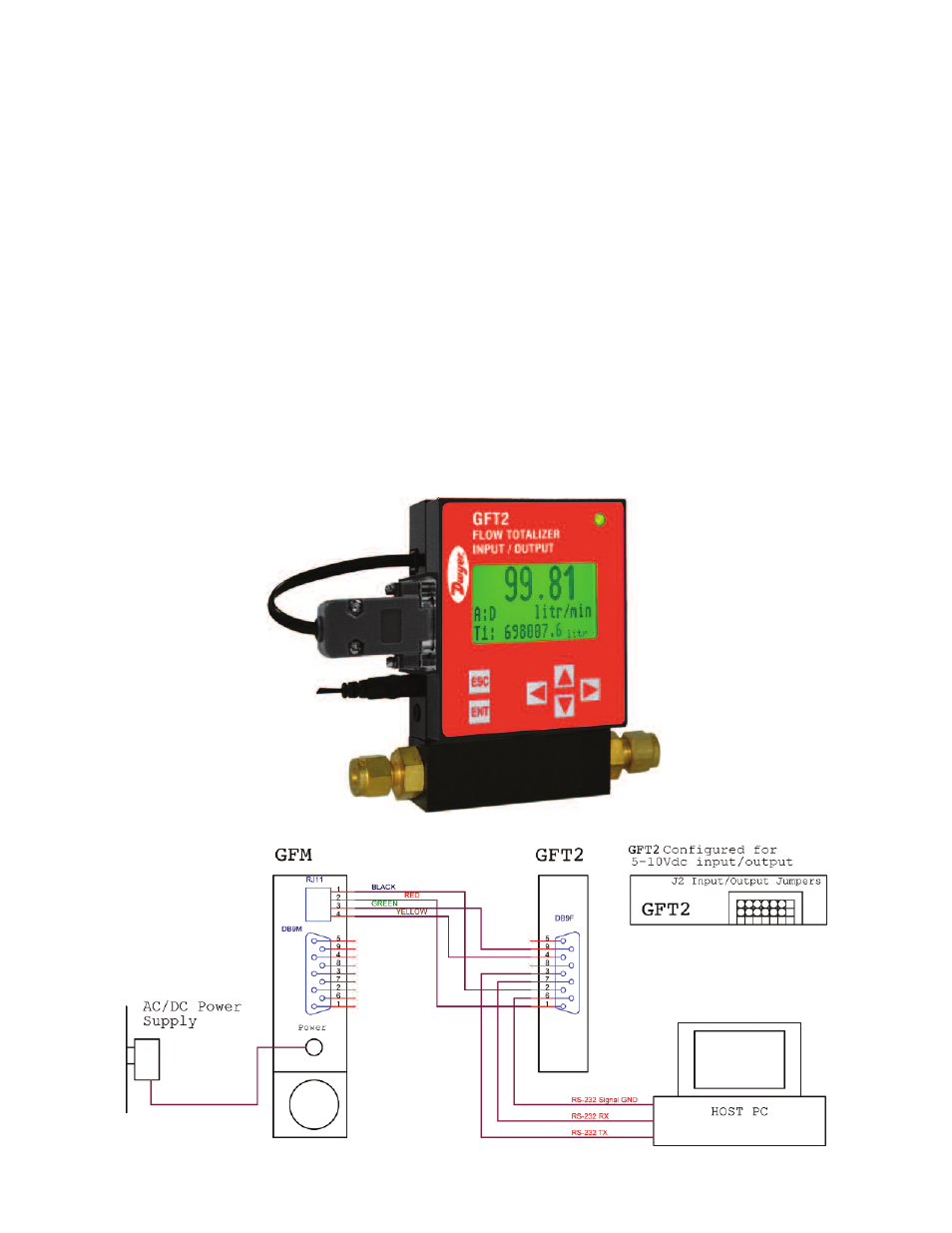
Connecting GFT2 to GFM Series Flow Meter
a) Mounting
Use the GFM mounting kit (See Table 4) to attach GFT2 to the GFM flow meter.
b) Electrical Connection
GFM flow meters have three different output interfaces (0 to 5, 5 to 10 VDC, 4 to
20 mA), which can be used to provide flow input signal to the GFT2.
Figure 32: Connecting GFT2 to the GFM using 0-5 VDC output from DB9 connector