Dwyer GFT2 User Manual
Page 5
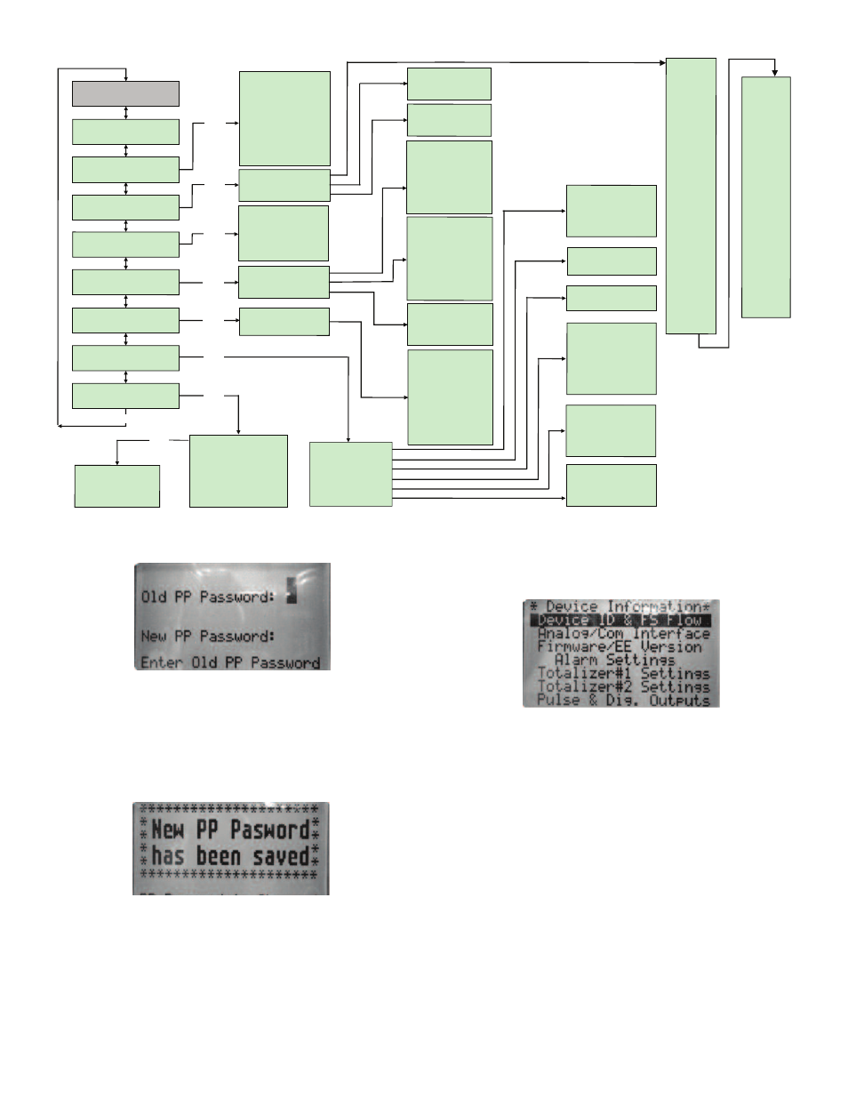
Once “Change PP Password” menu is selected, the following screen will appear:
In order to protect device configuration parameters when changing the PP
password, the old PP password must be entered.
NOTE: By default, the device shipped from the factory with Program Protection
(PP) password set to Zero (PP Disabled).
Once old and new passwords are entered, the firmware will prompt with a
confirmation message (see Figure 12) that the new password has been saved.
Submenu “Device Information”
This submenu contains information about the device’s main configuration
parameters. These items are informational only, not password-protected, and can
not be changed (read only).
Submenu “Measuring Units”
Use the “Engineering Units and K-Factor Menu” to navigate to “Measuring Units”
menu option. This option allows configuration of the flow meter/controller with the
desired units of measurement. These are global settings and determine what
appears on all process information screens and data log records. Units should be
selected to meet each particular metering need. A total of 47 different volumetric
and mass based engineering units are supported (See Table 4).
NOTE: Program the Measuring Units first because subsequent menus may be
based on the units selected. Once Flow Unit of Measure is changed, the Totalizer’s
Volume based Unit of Measure will be changed automatically.
Program Protaction (PP)
Change PP Password
Device Information
EngUnits & K-Factor
Totalizer Settings
Opt Output Settings
General Settings
Device Diagnostic
Alarm Settings
***** Main Menu *****
Up/Dn
Event Register Menu
Analog Input counts
Analog Output Value
LCD Back Light Set.
Pulse Output Queue
CPU Temperature
Device Diagnostic
Opt Output #1 Set
Opt Output #2 Set
Totalizer #1
Totalizer #2
Pulse Output
Flow Alarm Mode
Low Flow Alarm
High Flow Alarm
Flow Alarm Delay
Flow Alarm Latch
Measuring Units
UserDefined Units
K-Factor Settings
Device ID & FS Flow
Analog/Com Interface
Firmware/EE Version
Alarm Settings
Totalizer#1 Settings
Totalizer#2 Settings
Pulse & Dig. Outputs
Mated Device Info
General Settings
Display Mode
Screen Cycle Time
Screen Mask
Display Back Light
Display Contrast
Flow Meter
Flow Controller
Baud Rate Settings
RS-485 Bus Address
Full Scale Range
Low Flow Cut-off
Flow PowerUp Delay
Fluid Std. Density
Analog Output Cal.
Analog Input Cal.
Pilot Cal. Timer
Signal Condit. Mode
NRF Num. of Samples
NRF Time Interval
Aver.Filter Damping
FlowLinearizer Mode
Program SP Mode
PSP Loop Mode
PSP Steps Mask
PSP Steps Settings
Totalizer #1 Mode
Tot#1 Flow Start
Tot#1 Action Vol.
Tot#1 PowerOn Delay
Tot#1 Auto Reset
Tot#1 AutoRes Delay
Reset Totalizer #1
Totalizer #2 Mode
Tot#2 Configuration
Tot#2 Flow Start
Tot#2 Action Vol.
Tot#2 PowerOn Delay
Tot#2 Auto Reload
Tot#2 AutoRel Delay
Reset Totalizer #2
PulseOutput Mode
Pulse Flow Start
[Unit]/Pulse
Pulse Active Time
Disabled
Low F. Alarm
High F. Alarm
F. Range H-L
Total#1 Event
Total#2 Event
Pulse Output
Diagnostic
Manual On
UD Unit K-Factor
UD Unit Time Base
UD Unit Use Density
K-Factor Mode
Int. K-Factor Index
User Def'd K-Factor
%FS
ml/sec
ml/min
ml/hr
ml/day
litr/sec
litr/min
litr/hr
litr/day
m^3/sec
m^3/min
m^3/hr
m^3/day
f^3/sec
f^3/min
f^3/hr
f^3/day
gal/sec
gal/min
gal/hr
gal/day
gram/sec
gram/min
gram/hr
gram/day
kg/sec
kg/min
kg/hr
kg/day
lb/sec
lb/min
lb/hr
lb/day
Mton/min
Mton/hr
Igal/sec
Igal/min
Igal/hr
Igal/day
MilL/min
MilL/hr
MilL/day
bbl/sec
bbl/min
bbl/hr
bbl/day
User
Ent
Event Reg. Status
Event Latch Mask
Event Reg. Mask
Reset Event Reg.
Display Settings
Device Function
Communication Sett.
Device Calibration
Signal Conditioner
Program Set Point
Ent
Ent
Ent
Ent
Ent
Ent
Ent
Figure 10
Figure 11
Figure 12
Figure 13