Dwyer GFT2 User Manual
Page 7
d) Flow Alarm Action Delay (Numerical entry)
The Flow Alarm Action Delay is a time in seconds that the Flow Rate value remain
sabove the high limit or below the low limit before an alarm condition is validated.
Valid settings are in the range of 0 to 3600 seconds (default value is 0, no delay).
e) Flow Alarm Action Latch (Tabular entry)
The Flow Alarm Action Latch settings controls the Latch feature. If optically-isolated
output is assigned to the Flow Alarm Event, in some cases, the Flow Alarm Latch
feature may be desirable.
The following settings are available: Disable or Enable. By default, Flow Alarm is
non-latching. That means the alarm is indicated only while the monitored Flow
Value exceeds the specified set conditions.
Submenu “Totalizer #1”
GFT2 provides the user with two independent Programmable Flow Totalizers. The
total volume of the flowing fluid is calculated by integrating the actual instantaneous
fluid flow rate with respect to time. Totalizer #1 (main totalizer) value is stored in the
EEPROM and saved every (1) second. In case of power interruption, the last saved
Totalizer value will be loaded on the next power on cycle, so main totalizer reading
will not be lost. Use the “Totalizer Menu” to navigate to the “Totalizer #1” menu
option. The following settings are available for Totalizer #1 (see Figure 10).
a) Totalizer #1 Mode (Tabular entry)
This option determines whether Totalizer #1 is Enabled or Disabled. The following
selections are available: Enabled or Disabled. The default entry is Disabled.
Totalizer #1 Mode selections can be set with the UP and DN buttons and are
accepted by pressing ENT button.
NOTE: Before enabling the Totalizer, ensure that all totalizer settings are
configured properly. Totalizer Start values have to be entered in the currently active
Volumetric or Mass flow engineering unit. The Totalizer will not totalize until the
Process Flow Rate becomes equal to or more than the Totalizer Start value.
Totalizer Event values must be entered in currently active volume or mass based
engineering units. If the Totalizer Event at preset total volume feature is not
required, set Totalizer Event value to zero (default settings).
b) Totalizer #1 Flow Start (Numerical entry)
This option allows the totalizer to start at a present flow rate. The Totalizer #1 will
not totalize until the process flow rate becomes equal to or more than the Totalizer
#1 Flow Start value. The limit of required Totalizer #1 Flow Start value can be
entered in increments of 0.1% from 0 to 100% FS.
c) Totalizer #1 Action Volume (Numerical entry)
This option allows the user to activate preset required action when the totalizer
reaches a preset volume. Totalizer #1 Action Volume value must be entered in
currently active volume/mass based engineering units. Totalizer #1 action event
becomes true when Totalizer #1 reading is more or equal to preset "Totalizer #1
Action Volume”. If the Totalizer #1 Action at preset total volume feature is not
required, set “Totalizer #1 Action Volume” value to zero (default settings).
d) Totalizer #1 Power On Delay (Numerical entry)
Sometimes it is convenient to start the Totalizer only after specified power up delay
interval. Most of the mass flow meters and controllers require some warm up time
from the power up event in order to stabilize process variable output and get
accurate reading. “Totalizer #1 Power On Delay” option allows set specified time
interval which must elapse from the device power up event before Totalizer will be
activated. Valid settings are in the range of 0 to 3600 seconds (default value is 0,
no delay).
e) Totalizer #1 Auto Reset (Tabular entry)
This option allows to automatically reset Totalizer #1 when it reaches preset Action
Volume value. This feature may be convenient for batch processing, when
predefined volume of the fluid must be repeatedly dispensed into the process. The
following selections are available: Enabled or Disabled.
The default entry is Disabled. Totalizer #1 Auto Reset selections can be set with the
UP or DN buttons and are accepted by pressing ENT button.
f) Totalizer #1 Auto Reset Delay (Numerical entry)
This option may be desirable when “Totalizer #1 Auto Reset” feature is enabled.
Valid settings are in the range of 0 to 3600 seconds (default value is 0, no delay).
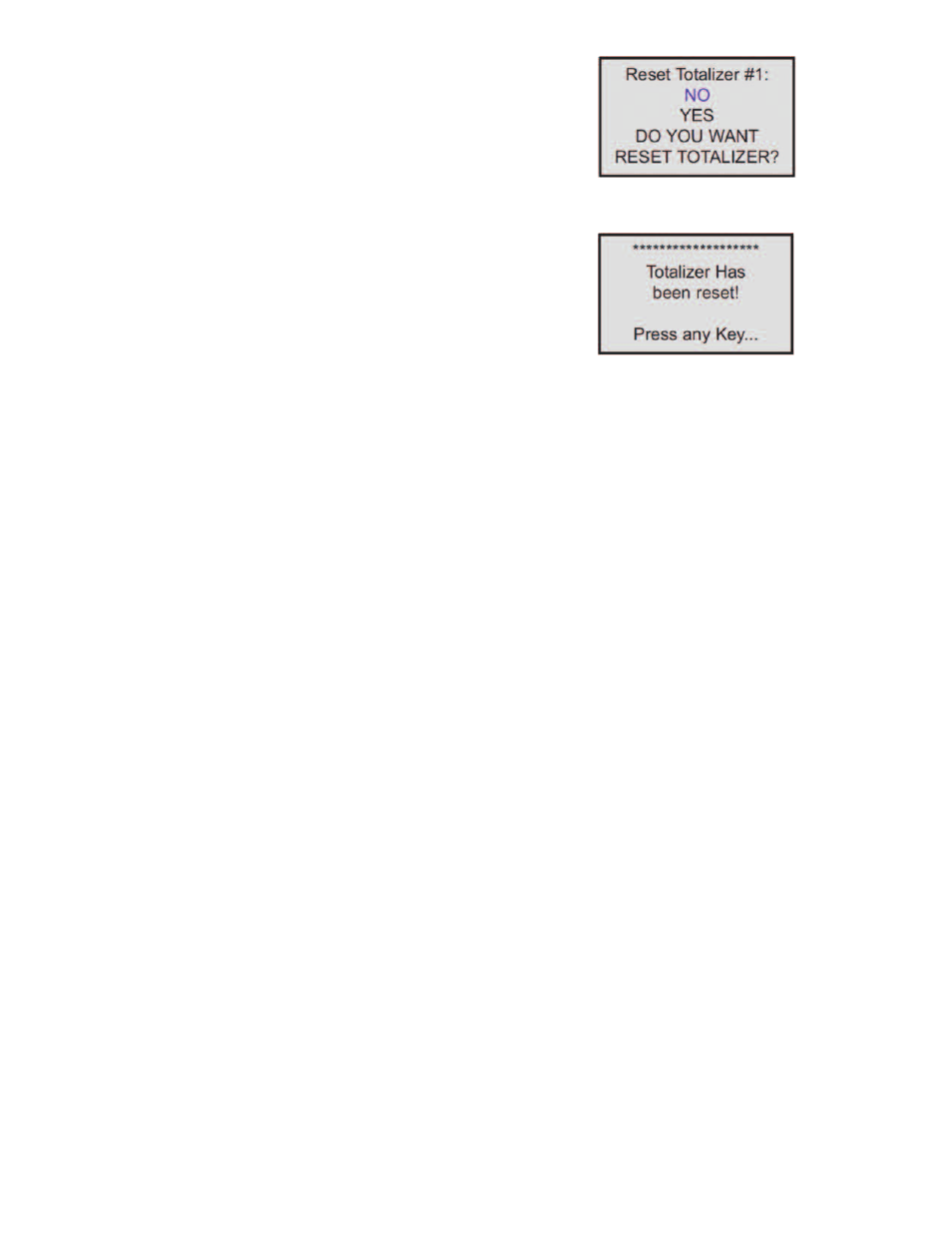
g) Reset Totalizer #1 (Numerical entry)
The Totalizers #1 reading can be reset by selecting “Reset Totalizer #1” menu
option. A typical display with Totalizer #1 Reset screen is shown in Figure 14.
Once the “YES” option is selected, Totalizer #1 will be reset and the following
confirmation screen will appear:
Submenu “Totalizer #2”
The Totalizer #2 (pilot totalizer) value is stored in the flow meter volatile memory
(SRAM) and saved every 100 milliseconds (0.1 second). In case of power
interruption, the Totalizer #2 volume will be lost (reset to zero). It is preferable to
use Totalizer #2 for short term process flow calculation (for example: batch
processing). Use the “Totalizer Menu” to navigate to “Totalizer #2” menu option. The
following settings are available for Totalizer #2 (see Figure 10):
a) Totalizer #2 Mode (Tabular entry)
This option determines whether Totalizer #2 is Enabled or Disabled. The following
selections are available: Enabled or Disabled. The default entry is Disabled.
Totalizer #2 Mode selections can be set with the UP and DN buttons and are
accepted by pressing ENT button.
NOTE: Before enabling the Totalizer, ensure that all Totalizer settings are
configured properly. Totalizer Start values must be entered in currently active
Volumetric or Mass flow engineering unit. The Totalizer will not totalize until the
process flow rate becomes equal to or more than the Totalizer Start value. Totalizer
Event values must be entered in currently active volume or mass based
engineering units. If the Totalizer Event at preset total volume feature is not
required, then set Totalizer Event value to zero (default settings).
b) Totalizer #2 Configuration (Tabular entry)
Totalizer #2 can be configured to count up or down. When configured to count
down, be sure “Totalizer #2 Action Volume” parameter is set to the desired value of
more than zero. In this case Totalizer #2 Action Event will be activated when the
totalizer counts down to zero. The following selections are available: Count UP or
Count DN. The default entry is Count UP. Totalizer #2 configuration selections can
be set with the UP and DN buttons and are accepted by pressing ENT button.
c) Totalizer #2 Flow Start (Numerical entry)
This option allows the start of the totalizer at a preset flow rate. The Totalizer #2 will
not totalize until the process flow rate becomes equal to or more than the Totalizer
#2 Flow Start value. The limit of required Totalizer #2 Flow Start value can be
entered in increments of 0.1% from 0 -100%FS.
d) Totalizer #2 Action Volume (Numerical entry)
This option allows the user to activate preset required action when totalizer reaches
a preset volume when totalizer configured to count up, or zero value when totalizer
configured to count down. Totalizer #2 Action Volume value must be entered in
currently active volume/mass based engineering units. When set to count up,
Totalizer #2 Action Event becomeS true when the totalizer #2 reading is more or
equal to preset “Totalizer #2 Action Volume”. If the Totalizer#2 Action at preset total
volume feature is not required, set “Totalizer #2 Action Volume” value to zero
(default settings).
NOTE: When Totalizer #2 is configured to count down, be sure “Totalizer #2 Action
Volume” value is set to any value more than zero.
e) Totalizer #2 Power On Delay (Numerical entry)
Sometimes it is convenient to start Totalizer only after specified power up delay
interval. Most of the mass flow meters and controllers require some warm up time
from the power up event in order to stabilize process variable output and get
accurate reading. “Totalizer #2 Power On Delay” option allows set a specified time
interval which must elapse from the device power-up event before Totalizer will be
activated. Valid settings are in the range of 0 to 3600 seconds (default value is 0,
no delay).
Figure 14
Figure 15