Modbus interface, Modbus interface 33, In the – Badger Meter Model IOG User Manual
Page 33
Modbus Interface
A subset of the standard Modbus commands is implemented to provide access into the data and status of the ER-500
monitor This feature is available on the ER-500 advanced models only The following Modbus commands are implemented:
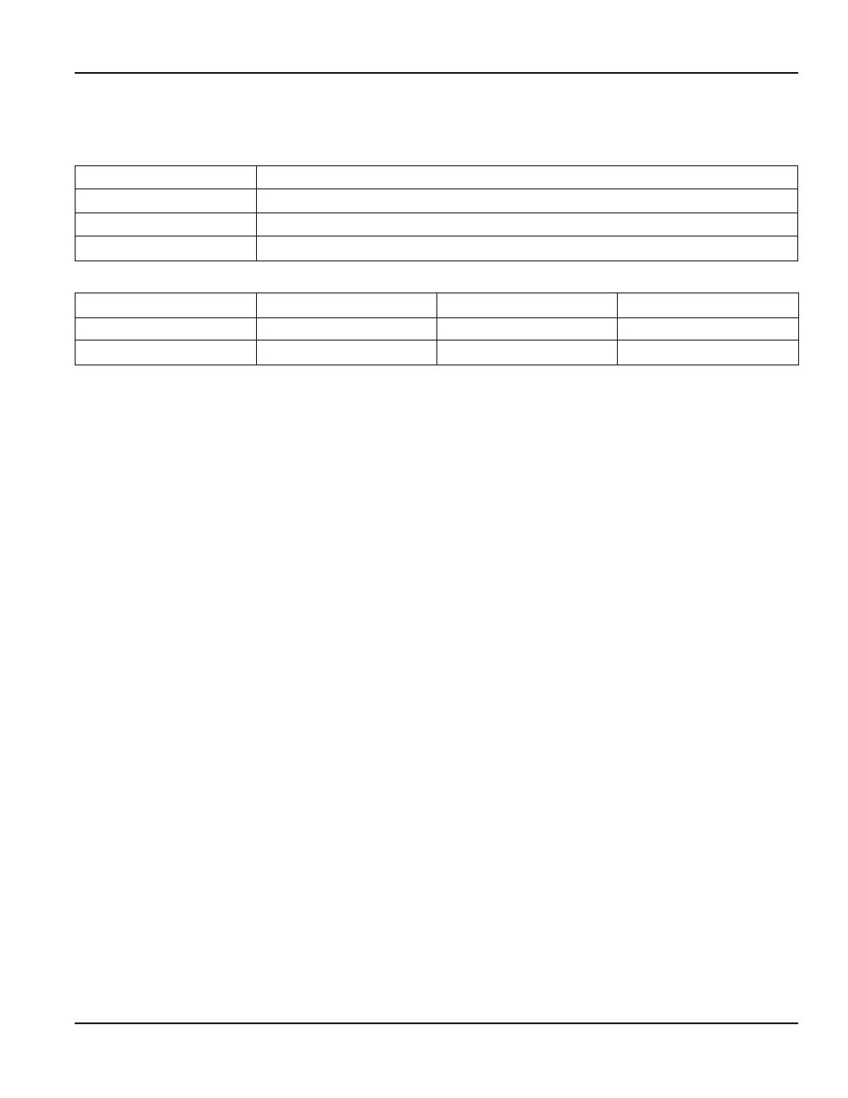
Command
Description
01
Read Coils
03
Read Holding Registers
05
Force Single Coil
Table 3: Modbus commands
Type
Bits
Bytes
Modbus Registers
Long Integer
32
4
2
Single Precision IEEE754
32
4
2
Table 4: Available data formats
Modbus Register / Word Ordering
Each Modbus holding register represents a 16-bit integer value (2 bytes) The official Modbus standard defines Modbus as a
‘big-endian’ protocol where the most significant byte of a 16-bit value is sent before the least significant byte For example,
the 16-bit hex value of ‘1234’ is transferred as ‘12’ ‘34’
Beyond 16-bit values, the protocol itself does not specify how 32-bit (or larger) numbers that span over multiple registers
should be handled It is very common to transfer 32-bit values as pairs of two consecutive 16-bit registers in little-endian word
order For example, the 32-bit hex value of ‘12345678’ is transferred as ‘56’ ‘78’ ‘12’ ‘34’ Notice the Register Bytes are still sent in
big-endian order per the Modbus protocol, but the Registers are sent in little-endian order
Other manufactures, store and transfer the Modbus Registers in big-endian word order For example, the 32-bit hex value of
‘12345678’ is transferred as ‘12’ ‘34’ ‘56’ ‘78’ It doesn’t matter which order the words are sent, as long as the receiving device
knows which way to expect it Since it’s a common problem between devices regarding word order, many Modbus master
devices have a configuration setting for interpreting data (over multiple registers) as ‘little-endian’ or ‘big-endian’ word order
This is also referred to as swapped or word swapped values and allows the master device to work with slave devices from
different manufactures
If, however, the endianness is not a configurable option within the Modbus master device, it’s important to make sure it
matches the slave endianess for proper data interpretation The ER-500 actually provides two Modbus register maps to
accommodate both formats This is useful in applications where the Modbus master cannot be configured for endianness
User Manual
Page 33
August 2013