Figure 14 – Badger Meter Model IOG User Manual
Page 19
JP1
JP2
JP3
Input
Total P
ulse
Sig
nal
P1
JP1
JP2
JP3
Input
Total P
ulse
Sig
nal
P1
Freq. In
4-20mA
Iso Total Pluse
TR_B
TR_A
RS485 Gnd
Setpoint 1
Setpoint 2
Gnd
+
–
+
–
+
–
Total Reset
OC Total Pluse
Signal Gnd
TB1
Mag
Pulse
Iso
OC
Low
High
Isolated Output
Total Pulse
Internal
–V
2.2…10K
Pull-up
Resistor
V
CC
100 mA
Maximum
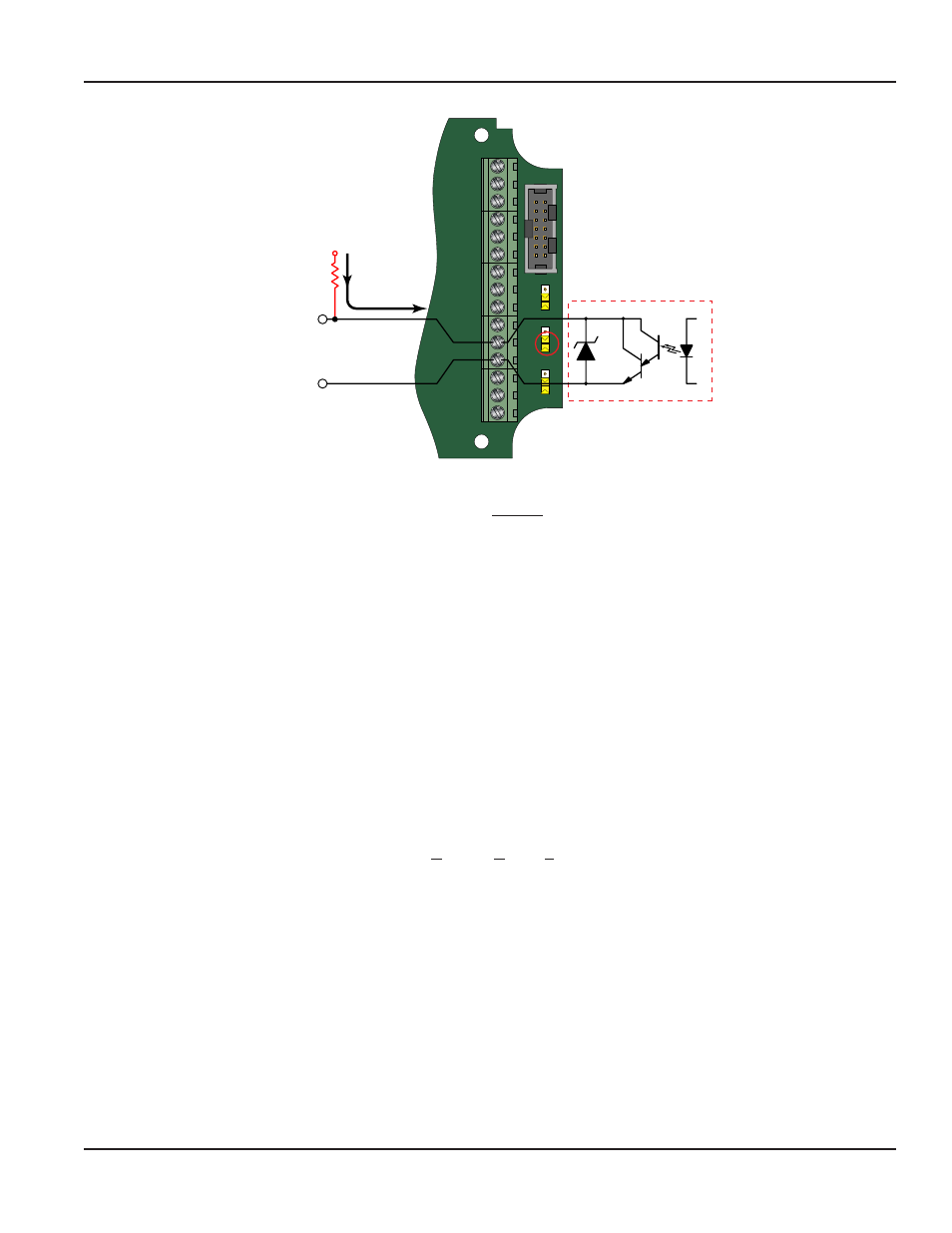
Figure 14: Opto-isolated open collector connections
Both outputs have a maximum current capacity of 100 mA and require a pull-up resistor The value of the pull-up resistor is
dependent on the supply voltage and the maximum current required by the load device
Flow 20 mA (Fl=20MA)
Basic Function
When the display is operated using loop power, the flow rate that corresponds to 20 mA must be set This setting normally
represents the maximum rate of the flow sensor connected to the display but other entries are possible
At the flow at 20 mA Fl=20mA prompt, press the ENTER button once The current setting begins to flash If the current setting
is correct, press the ENTER button to advance to the next parameter
If the current setting requires a change, use the
▲ arrow button, increment the display digit until it matches the first digit of
the desired maximum flow value Next press the
► arrow button to advance to the next digit and using the ▲ arrow button,
increment the second display digit until it matches the second digit of the desired value Repeat this step until the maximum
flow at 20 mA is entered Press the ENTER button once to save the new flow value
4-20 mA Calibration (4-20Cal)
Extended Function
This menu item allows the fine adjustment of the Digital to Analog Converter (DAC) that controls 4-20 mA output The
4-20 mA output is calibrated at the factory and under most circumstances does not need to be adjusted If the output
needs to be adjusted for whatever reason the 4-20 mA calibration procedure is used
The DAC used in the ER-500 is an 12 bit device so the valid entries range from 0 to 4095
4 mA ADJUSTMENT (4mA Out)
To set the 4 mA value, connect an ammeter in series with the loop power supply as shown in
prompt, press the ENTER button once The display now shows a steady "NO" indication Press the
▲ arrow button to
change to a YES display and then press the ENTER button The 4 mA DAC setting is typically between 35 and 50 Using
the
▲ and ► arrow buttons while monitoring the ammeter, adjust the 4 mA value to obtain a 4 mA reading on the
ammeter The
▲ arrow button increases the DAC value and the ► arrow button decreases the DAC value. When a
steady 4 mA reading is obtained on the ammeter, press the ENTER button to lock in this value and move to the
20 mA adjustment
User Manual
Page 19
August 2013