Figure 13: open drain connections, Figure 13: open drain connections 18, See figure 13 ) – Badger Meter Model IOG User Manual
Page 18
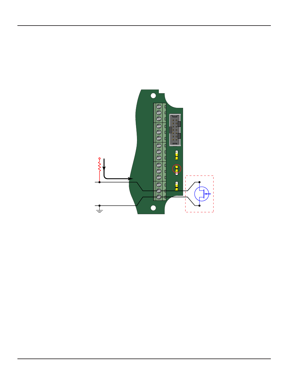
Totalizer Pulse Output (PulsOut)
Basic Function
The pulse output PulsOut parameter can be either Enabled or Disabled When enabled this output generates a fixed width 30
mS duration pulse every time the least significant digit of the totalizer increments The amplitude of the pulse is dependent
on the voltage level of the supply connected to the pulse output and is limited to a maximum 28V DC
The ER-500 provides two types of totalizer pulses The basic open drain FET output
provides a ground referenced output pulse
that swings between about 0 7V DC and V
CC
(See
JP1
JP2
JP3
P1
Freq. In
4-20mA
Iso Total Pluse
TR_B
TR_A
RS485 Gnd
Setpoint 1
Setpoint 2
Gnd
+
–
+
–
+
–
Total Reset
Total Pluse
Signal Gnd
Mag
Pulse
Iso
OC
Low
High
Input
Total P
ulse
Sig
nal
TB1
Open Drain FET
Total Pulse Output
2.2…10K
Pull-up
Resistor
V
CC
Internal
100 mA
Maximum
Figure 13: Open drain connections
The isolated pulse output (ISO),
, is again an open collector output with the emitter of the transistor connected to the
negative output terminal and is not referenced to ground This output is optically isolated from the input signal for systems
that require a totally isolated output pulse
ER-500 Flow Monitor
Page 18
August 2013