Figure 15: 4-20 ma calibration setup, Figure 15: 4-20 ma calibration setup 20, Temperature – Badger Meter Model IOG User Manual
Page 20: Ac+dc
P1
Freq. In
4-20mA
Iso Total Pluse
TR_B
TR_A
RS485 Gnd
Setpoint 1
Setpoint 2
Gnd
+
–
Total Reset
OC Total Pluse
Signal Gnd
TB1
Mag
Pulse
Iso
OC
Low
High
+
+
–
–
Input
Total P
ulse
Sig
nal
JP1
JP2
JP3
4-20 mA
Current Loop
(10…28V DC)
POWER
SUPPLY
10A MAX
FUSED
400mA
FUSED
CAT III
1000V
HOLD
MIN MAX
REL
Hz % ms
RANGE
AutoHOLD FAST MIN MX
LOGGING
YES
CANCEL
SAVE
NO
SETUP
µA
mA
A
W
V
TEMPERATURE
COM
OFF
nS
W
VIEW MEM
CLEAR MEM
V
dB
mV
dB
ac+dc
V
ac+dc
A
mA
mV
ac+dc
mA
A
µA
ac+dc
µA
°C
°F
MEM
HM
MS
51000
AUTO MANUAL
%
FA S T M A X M I N AV G
0
0
LOG
HOLD
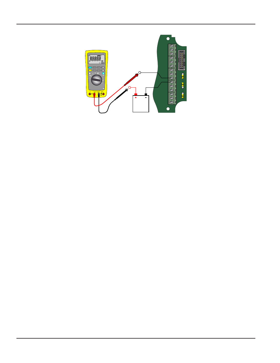
Figure 15: 4-20 mA calibration setup
20 mA ADJUSTMENT (20mAOut)
The 20 mA adjustment is performed using the same procedure as the 4 mA adjustment While monitoring the ammeter,
adjust the 20 mA DAC value to obtain a 20 mA reading The
▲ arrow button increases the DAC value and the ►
arrow button
decreases the DAC value. When a steady 20 mA reading is obtained on the ammeter, press the ENTER
button to lock in this value and move to the next parameter
4-20 mA TEST (4-20Tst)
The ER-500 monitor contains a diagnostic routine that allows the simulation of mA output values between 4 and 20 to
check output tracking At the 4-20 Tst prompt the current is shown as a flashing number Use the
▲ arrow button to
increase the simulated mA output in increments of 1 mA The
► arrow button decreases the mA output. The ammeter
should track the simulated mA output If a 4-20 mA test is not necessary, press the ENTER button once to move to the
next parameter
NOTE:
N
Pressing the ENTER button when the monitor is in test mode causes the monitor to exit the test mode and move on
to the next programming parameter
Linearization (Linear)
Extended Function
Enhanced accuracy is obtained by linearization of the display The linearization function accepts a maximum of ten
points Linearization requires additional calibration data from the meter to be used with the monitor Typically, calibration
information can be obtained in three, five, and ten points from the flow meter’s manufacturer If linearization is not
needed, press the
► arrow button to advance to the next parameter The maximum number of linearization
points is 10
Number of Points (Lin Pts)
At the Linear prompt, press the ENTER button once The linear points Lin Pts value is displayed If the number of points
is set to 0, linearization is disabled Press the ENTER button and the most significant digit of the number of points entry
begins to flash The first number can either be a 1 or a 0 only Use the
▲ arrow button to change the first digit Press the
► arrow button once to move to the least significant digit
NOTE:
N
If a number other than 0 or 1 is entered in this field the display flashes "Limit" indicating that an over range value has
been entered when the ENTER button is pressed
Again, the
▲ arrow button increments the value When the number of points has been input, press the ENTER button
once to move to the first linear points frequency entry
ER-500 Flow Monitor
Page 20
August 2013