Figure 18: set point actions, Figure 18: set point actions 24 – Badger Meter Model IOG User Manual
Page 24
If the current setting requires a change, press the
► arrow button to advance to the first digit of the desired set point
value Once the correct place is reached use the
▲ arrow button to increment the digit until it matches the first number
of the desired set point Use the
► arrow button to advance to the next digit of the desired set point value then use the
▲ arrow button, increment the display digit until it matches the next digit of the desired set point Repeat this step for
the all the digits of the set point and then press the ENTER button once to save the new set point and advance to the
next parameter
Hysteresis 1 (HystSP1)
Extended Function (Advanced Version Only)
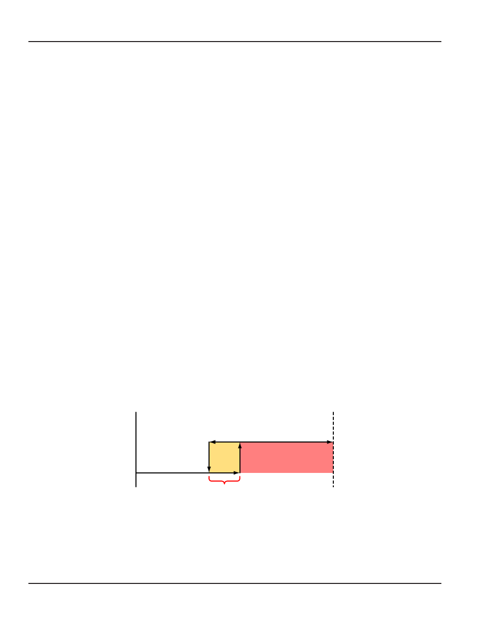
Hysteresis is used to modify how the output transistor reacts around a set point by taking recent history into account
Hysteresis prevents an output from turning on and off rapidly when the programed flow rate is at or very near the
set point
For example, a low flow alarm is set to activate when the flow falls below a pre programed point When the flow is
reduced to the set point, even minute changes of flow above the set point turns the output off disabling the alarm
Without hysteresis, if the flow rate fluctuates slightly above and below the set point the output rapidly cycles between on
and off states
Another example is a thermostat controlling a heater The thermostat turns the heater on when the temperature drops
below “A” degrees, but won’t turn it off until the temperature rises above “B” degrees The temperature between “A” and
“B” is know as the hysteresis Thus the on/off output of the thermostat to the heater when the temperature is between “A”
and “B” depends on the “history” of the temperature This prevents rapid switching on and off as the temperature drifts
around the set point
Refer to the graphical representation of the hysteresis setting as shown in
. The hysteresis value is set using the
same units as the rate units are entered
At the hysteresis HystSP1 prompt, press the ENTER button once The most significant digit of the current setting begins to
flash If the current setting is correct, press the ENTER button to advance to the next parameter
If the current setting requires a change, press the
► arrow button to advance to the first digit of the desired hysteresis
value Once the correct place is reached use the
▲ arrow button to increment the digit until it matches the first number
of the desired hysteresis Use the
► arrow button to advance to the next digit of the desired hysteresis value then use
the
▲ arrow button, increment the display digit until it matches the next digit of the desired hysteresis Repeat this step
for the all the digits of the hysteresis and then press the ENTER button once to save the new hysteresis and advance to
the next parameter
Minimum
Flow
Maximum
Flow
Output ON
OFF S
etpoin
t
ON S
etpoin
t
Hysteresis
Output OFF
Figure 18: Set point actions
NOTE:
N
Neither the set point nor the hysteresis values are checked against the maximum flow rate to see if they are
appropriate Care should be used when entering these values, especially in critical applications, as it is possible to
enter inappropriate values preventing the outputs from working as expected
ER-500 Flow Monitor
Page 24
August 2013