Figure 6: loop power connections, Power connections, Power connections 10 – Badger Meter Model IOG User Manual
Page 10: Figure 6: loop power connections 10
The ILR transmitter also has a secondary (Auxiliary) set of pulse output wires Either pair can be used to connect to the ER-500
The connections are:
ILR Wires
ER-500 Terminals
Reed Switch Bank (Primary)
Reed Switch Bank (Auxiliary)
Freq. In +
White
Blue
Freq. In -
Green
Black
Table 1: Input connections
Power Connections
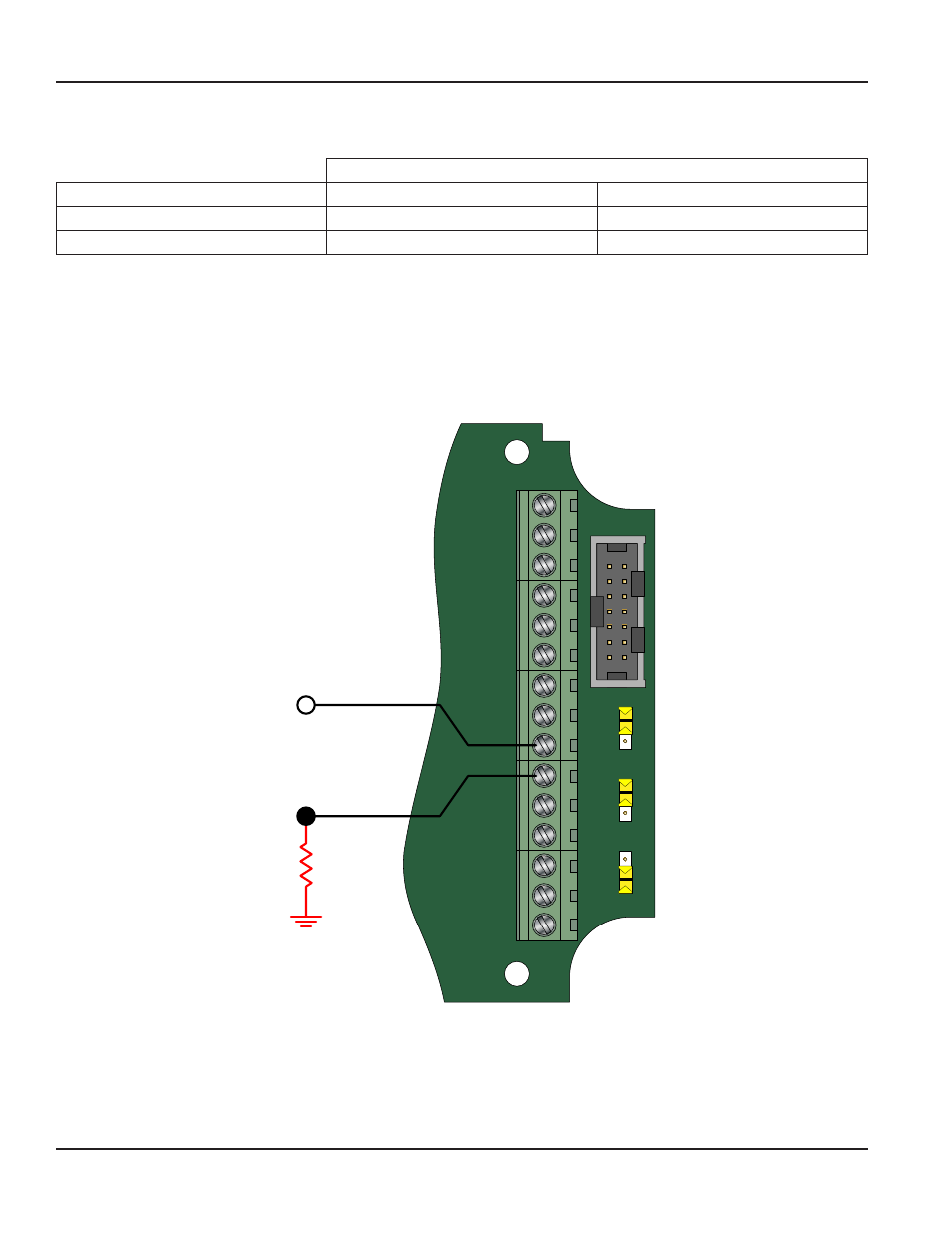
The ER-500 has two power supply options The first power supply is an internal lithium 3 6V DC D size cell that powers
the monitor for about 6 years when no outputs are used The monitor can also derive power from a 4-20 mA current loop
(See
) If the current loop is used, a sensing circuit within the monitor detects the presence of the current loop and
automatically disconnects the battery from the circuit
JP1
JP2
JP3
Input
Total P
ulse
Sig
nal
P1
Freq. In
4-20mA
Iso Total Pluse
TR_B
TR_A
RS485 Gnd
Setpoint 1
Setpoint 2
Gnd
+
–
+
–
+
–
Total Reset
OC Total Pluse
Signal Gnd
TB1
Mag
Pulse
Iso
OC
Low
High
4-20 mA
Current Loop
(10 …28V DC)
Load
10…28V DC
Figure 6: Loop power connections
ER-500 Flow Monitor
Page 10
August 2013